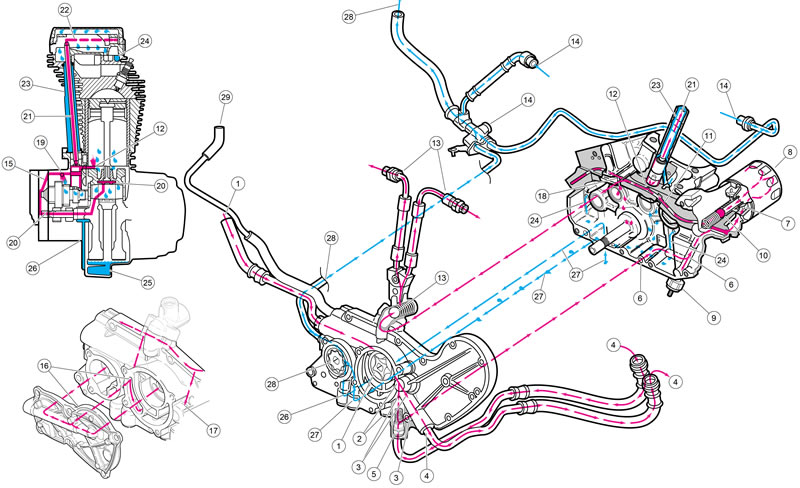
Note. See Figure 3-13. The paragraph numbers correspond with the callouts.
1. Oil is gravity-fed from the oil tank to the gerotor-style oil pump through a feed hose and internal passages. Oil enters the inlet cavity of the feed pump. See 3.21 OIL PUMP: XR 1200X.
2. The feed pump transfers oil through a passage in the pump housing to a point where it splits direction. The pump is capable of delivering more oil than can flow through the engine. When oil pressure exceeds 50 psi (345 kPa), the bypass valve opens. Oil circulates into the inlet side of the feed pump.
3. Part of the oil passes through an internal passage toward the oil filter and part heads toward the oil cooler line.
4. Oil exits the oil pump housing through a line connected with quick connect fittings and enters the lower end of the oil cooler. Oil flows up through the oil cooler and exits the upper end where it flows back to the oil pump housing.
5. A thermostat is located where the oil cooler return line connects to the oil pump housing. The thermostat begins to open when the oil reaches 190°F (88°C). As it opens, oil from the cooler flows past while oil flow from the feed pump is restricted. This provides cooled oil for engine lubrication. When the thermostat is full open, oil flow is sealed off from the pump. All oil then passes through the oil cooler, past the thermostat, and towards the oil filter.
6. Oil flowing to the filter passes through an internal passage to the oil filter mount.
7. Oil flows through the filter mount cavity to the oil filter.
8. Oil enters the peripheral cavity of the oil filter, passes through the filtering medium into the central cavity of the oil filter, and flows into the filter adapter (fitting which attaches the filter to filter mount).
9. Adequate oil pressure in the filter supply passage activates the oil pressure indicator lamp switch and shuts off the oil pressure indicator lamp.
10. Oil flowing from the filter adapter opens the check ball. The check ball opens at 5-7 psi (34-48 kPa) oil pressure.
11. With the check ball open, oil flows into the crankcase feed galley.
12. Oil flows through the feed galley in the crankcase to the tappet blocks and hydraulic lifters. Cross-drilled passages intersect the main feed galley and carry oil to each hydraulic lifter. From this cavity, oil is also fed to the piston jets.
13. Also from the feed galley in the crankcase, oil flows through a cross drilled passage to the check valve assembly. Then to the cylinder heads through flexible lines. Oil flows across the cylinder heads and through passages that surround the exhaust ports. Oil exits each cylinder head near the exhaust port.
14. Oil exiting the heads flows to the return oil manifold where it is mixed with the scavenge oil from the scavenge pump and is pushed back to the tank.
15. Oil flows from the feed galley through an intersecting passage in the oil pump body and cam support. Oil flow is then routed to the outer bearing of the rear intake camshaft. A cast-in passage allows oil into a cavity that surrounds the end of the pinion gear shaft.
16. From the cavity at the pinion shaft end, oil enters the center hole in the oil pump rotor cover. The center hole intersects a passage that carries oil to the outer bearings of the front intake camshaft and rear exhaust camshaft.
17. The outer bearing of the front exhaust camshaft is lubricated through a drilled passage that intersects with the feed galley.
18. Crankcase end of bearings of the cams are fed through holes in the camshaft.
19. A small amount of oil flows from the feed galley in the right crankcase through a restricted orifice. This sprays the oil onto the rear intake cam gear in the gearcase. Oil is transferred to the teeth of all the cam gears through the gear meshing action.
20. Oil enters a hole in the end of the pinion gear shaft and travels to the right flywheel where it is routed through the flywheel to the crank pin. Oil is forced through the crank pin to properly lubricate the rod bearing assembly.
21. Oil flows up passages in the pushrods to the rocker arm shafts and bushings.
22. The valve stems are lubricated by oil supplied through drilled oil holes in the rocker arms.
23. Oil collected in the pushrod areas of the cylinder heads flows down the pushrod covers to the tappet blocks. It drains through holes in the tappet blocks and provides lubrication to the gearcase components. Oil then settles to the bottom of the gearcase and is collected by the scavenge pump.
24. Feed oil to the rocker area is returned to the gearcase through a passage in the cylinder head, cylinder, and crankcase.
25. Oil collected in the sump is splash-fed to the pistons, cylinder walls and flywheel components.
26. Oil in the sump returns to the scavenge pump through an internal passage located in the rear of the sump housing. The downward stroke of the pistons and the scavenge pump feed oil to the oil pump.
27. Oil collected in the gearcase passes through a passage in the oil pump body and cam support and is also collected by the scavenge pump.
28. The scavenge pump pushes the collected oil back to the oil tank.
29. Crankcase vents to oil tank.

Figure 3-13. Lubrication diagram: XR 1200X (Red=feed oil, Blue=return oil)
