1. Make sure all oil line connections are tight. Verify that lines are not pinched or damaged.
2. Check level and condition of oil in tank. Pressure will be affected if oil is diluted. In freezing weather, proper circulation of oil can be affected if the oil feed line becomes clogged with ice or sludge.
3. Check for a grounded oil pressure switch wire [120] or faulty switch if oil pressure indicator light fails to go out with engine running. See 3.6 ENGINE LUBRICATION SYSTEM, 3.24 OIL TANK and 6.31 OIL PRESSURE SWITCH.

Figure 3-137. Oil pump: XR 1200X: 1. Oil pump rotor cover; 2. O-rings, rotor cover; 3. Retainer; 4. O-ring, internal (1 each fitting); 5. Line connector fitting, return oil; 6. O-ring, external (1 each fitting); 7. Scavenge gerotor set; 8. Feed gerotor set; 9. Line connector fitting, supply oil; 10. Vent line fitting; 11. Oil pump/gearcase housing; 12. O-ring; 13. Check valve housing, cylinder head oil; 14. O-ring; 15. Fastener (2); 16. Plug; 17. O-ring; 18. Spring; 19. Check ball; 20. Gasket; 21. Line connector fitting, oil to cooler; 22. Thermostat (oil from cooler); 23. Plugs; 24. Bypass valve shuttle; 25. Spring, bypass valve; 26. O-ring; 27. Plug; 28. Fastener (6)
Disassembly
Note. The oil pump can be removed with engine in frame and without removing gearcase cover.
1. Remove the exhaust system. See 4.14 EXHAUST SYSTEM: XR 1200X.
2. Drain oil from oil tank.
3. Place pan under oil pump to collect oil.
4. See Figure 3-138. Remove nine fasteners (1) and remove gearcase and oil pump cover (2).

Figure 3-138. Oil pump cover: XR 1200X
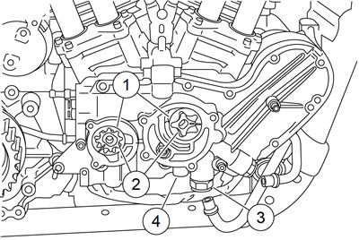
5. See Figure 3-139. Remove oil cooler rigid lines (3) from gearcase cover. See 3.12 PRECISION COOLING SYSTEM: XR 1200X, Oil Pump Lines.

Figure 3-139. Oil pump rotor cover: XR 1200X: 1. Cover screw (6); 2. Rotor cover; 3. Oil cooler rigid lines
6. Remove six screws (1) and remove oil pump cover (2). Discard cover O-rings.
Note. If oil pump rotors are to be re-used, they must be installed in the original location and orientation as when they are removed. Failure to do so can result in accelerated wear and possible engine failure.
7. See Figure 3-140. Wipe the oil film from the exposed surfaces of the rotors (1, 2) and mark each rotor using a permanent marker to aid in reassembly.

Figure 3-140. Oil pump: XR 1200X: 1. Outer rotor; 2. Inner rotor; 3. Thermostat; 4. Bypass valve plug
Note. The surface tension of the remaining oil film will make the rotors "stick" against the bottom of the bore. Never use a metallic tool to remove oil pump rotors. This could result in damage requiring rotor or gearcase cover replacement.
8. Grasp the outer rotor (1) of each stage and pull from housing bore.
9. Remove each inner rotor (2).
10. Remove the thermostat fitting (3) and spring.
11. Remove the plug and bypass valve components (4).
12. If necessary, remove remaining line connector fittings from gearcase cover.
13. Remove and discard all used O-rings.
Cleaning and inspection
Warning! Compressed air can pierce the skin and flying debris from compressed air could cause serious eye injury. Wear safety glasses when working with compressed air. Never use your hand to check for air leaks or to determine air flow rates.
1. Clean all parts in cleaning solvent. Blow out holes and oil passages with compressed air.
2. See Figure 3-141. Inspect both gerotor sets for wear.
- a. Mesh pieces of each set together as shown.
- b. Use a feeler gauge to determine clearance.
- c. The SERVICE WEAR LIMIT between gerotors is 0.004 in (0.102 mm). Replace gerotors as a set if clearance exceeds this dimension.
- d. Measure thickness of feed gerotors with a micrometer. Replace gerotors as a set if they are not the same thickness.

Figure 3-141. Gerotor wear limits: 1. Outer gerotor; 2. Inner gerotor; 3. Wear limit
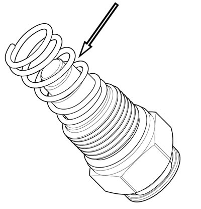
3. See Figure 3-142. Inspect thermostat spring for distortion or cracks. Inspect rubber seal for damage. Replace thermostat assembly as necessary.

Figure 3-142. Thermostat: XR 1200X
Assembly
| FASTENER | TORQUE VALUE | |
| Gearcase housing plug | 108-156 in·lbs | 12.2-17.6 Nm |
| Oil pump rotor cover screw: XR 1200X | 90-120 in·lbs | 10.2-13.6 Nm |
| Gearcase cover fastener | 90-120 in·lbs | 10.2-13.6 Nm |
Note. Used O-rings can leak. Always install new O-rings when performing repairs.
1. Install new internal O-rings in each line connector fitting.
2. Install new external O-rings on all connector fittings that have been removed.
Note. Apply a light coat of new engine oil to the shuttle valve components and oil pump rotors during assembly.
3. See Figure 3-140. Install bypass valve components (4). Tighten plug to 108-156 in·lbs (12.2-17.6 Nm).
4. Install thermostat and oil cooler line fitting (3).
Note. If oil pump rotors are to be re-used, they must be installed in the original location and orientation. Make sure the mark made during disassembly is visible when installing the rotors. Failure to do so can result in accelerated wear and possible engine failure.
5. Install each outer rotor (1) in its original location.
6. Install each inner rotor (2) in its original location.
7. See Figure 3-139. Install new O-rings in oil pump rotor cover and install cover using six fasteners (1). Tighten fasteners to 90-120 in·lbs (10.2-13.6 Nm).
8. Install oil cooler rigid lines (3) to quick connect fittings. See 3.12 PRECISION COOLING SYSTEM: XR 1200X, Oil Pump Lines.
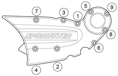
9. See Figure 3-143. Install oil pump/cam support housing cover. Secure with 9 socket fasteners. Tighten in the sequence shown to 90-120 in·lbs (10.2-13.6 Nm).

Figure 3-143. Oil pump cover torque sequence: XR 1200X
10. Install the exhaust system. See 4.14 EXHAUST SYSTEM: XR 1200X.
