1. Make sure all oil line connections are tight. Verify that lines are not pinched or damaged.
2. Check level and condition of oil in tank. Pressure will be affected if oil is diluted. In freezing weather, proper circulation of oil can be affected if the oil feed line becomes clogged with ice or sludge.
3. Check for a grounded oil pressure switch wire [120] or faulty switch if oil pressure indicator light fails to go out with engine running.
See 3.6 ENGINE LUBRICATION SYSTEM, 3.24 OIL TANK and 6.31 OIL PRESSURE SWITCH.

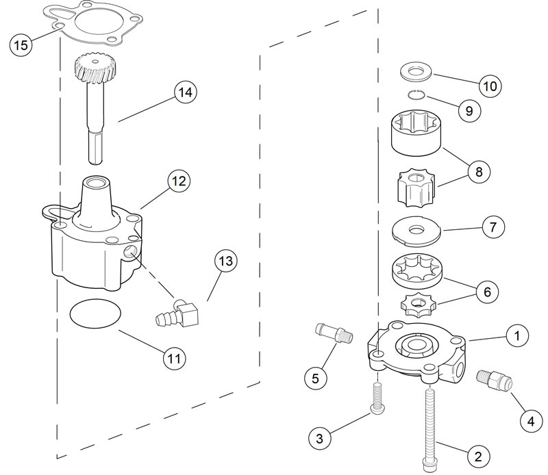
Figure 3-134. Oil pump: XL models: 1. Oil pump cover; 2. Screw w/ washer (2); 3. Torx screw (2); 4. Connector; 5. Hose fitting; 6. Feed gerotor set; 7. Gerotor separator plate; 8. Scavenge gerotor set; 9. Retaining ring; 10. Thrust washer; 11. O-ring; 12. Oil pump body; 13. Elbow fitting; 14. Gear shaft; 15. Gasket
Removal
Note. The oil pump can be removed with engine in frame and without removing gearcase cover.
1. Drain oil from oil tank.
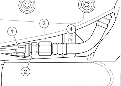
Note. See Figure 3-135. Do not remove oil pump feed fitting (2) from the pump (1). Hold oil pump feed fitting and loosen large high pressure hose fitting nut (3). Then remove high pressure hose (4) from oil pump feed fitting.

Figure 3-135. Oil pump feed hose: 1. Oil pump; 2. Oil pump feed fitting; 3. High pressure hose fitting nut; 4. High pressure feed hose (to oil filter)
2. See Figure 3-135. Remove high pressure feed hose (4) from oil pump (1).
Note. See Figure 3-134. The oil pump is designed to be removed as a complete assembly by removing the two long screws (2) at opposite corners of the pump. The other two screws (3) hold the pump together so that it may be removed and installed as a unit.
3. See Figure 3-134. Carefully remove two screws (2) that secure oil pump to crankcase. Pump will drop with screws removed. Discard mounting gasket (15).
4. Disconnect and tag the two remaining oil hoses from the pump.
Disassembly
1. See Figure 3-134. Remove two Torx screws (3). Lift cover (1) off body (12). Remove and discard O-ring (11).
2. Slide both pieces of feed gerotor set (6), separator plate (7) and both pieces of scavenge gerotor set (8) off gear shaft (14).
3. Remove and discard retaining ring (9). Remove thrust washer (10) and gear shaft.
Cleaning and inspection
Warning! Compressed air can pierce the skin and flying debris from compressed air could cause serious eye injury. Wear safety glasses when working with compressed air. Never use your hand to check for air leaks or to determine air flow rates.
1. Clean all parts in cleaning solvent. Blow out holes and oil passages with compressed air.
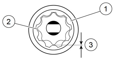
2. See Figure 3-136. Inspect both gerotor sets for wear.
- a. Mesh pieces of each set together as shown.
- b. Use a feeler gauge to determine clearance.
- c. The SERVICE WEAR LIMIT between gerotors is 0.004 in (0.102 mm). Replace gerotors as a set if clearance exceeds this dimension.
- d. Measure thickness of feed gerotors with a micrometer. Replace gerotors as a set if they are not the same thickness.

Figure 3-136. Gerotor wear limits: 1. Outer gerotor; 2. Inner gerotor 3. Wear limit
Assembly
| FASTENER | TORQUE VALUE | |
| Oil pump cover screws | 70-80 in·lbs | 7.9-9.0 Nm |
Note. Liberally coat all moving parts with clean engine oil to lubricate at start-up.
1. See Figure 3-134. Install gear shaft (14) through oil pump body (12). Position thrust washer (10) over end of shaft. Install new retaining ring (9) into groove in shaft.
2. Insert inner gerotor of the scavenge gerotor set (8) over gear shaft.
3. Place outer gerotor over inner to complete scavenge set.
4. Position separator plate (7) into case and line up slots on perimeter with tabs inside oil pump body.
5. Place feed gerotor set (6) over gear shaft.
6. Install a new O-ring (11) into groove in oil pump cover (1). Place cover onto pump body. Install two Torx cover screws (3). Tighten to 70-80 in·lbs (7.9-9.0 Nm).
Installation
| FASTENER | TORQUE VALUE | |
| Oil pump to crankcase screw | 125-150 in·lbs | 14.1-16.9 Nm |
| Oil pump feed fitting | 100-120 in·lbs | 11.3-13.6 Nm |
| Oil pump high pressure feed hose to crankcase fitting | 60-90 in·lbs | 6.8-10.2 Nm |
| Oil pump high pressure feed hose fitting nut | 85-105 in·lbs | 9.6-11.8 Nm |
1. See Figure 3-134. Place new mounting gasket (15) in position.
2. Secure pump to crankcase with two screws (2). Tighten to 125-150 in·lbs (14.1-16.9 Nm).
Note. Use new hose clamps to secure oil tank feed hose and vent hose to oil pump fittings. If fittings were removed, use TEFLON PIPE SEALANT or HYLOMAR on fitting threads.
3. Install hoses on oil pump. Attach oil tank feed hose to hose fitting (5) with new clamp. Attach oil tank vent hose to elbow fitting (13) with new clamp.
4. See Figure 3-135. If oil pump feed fitting (2) was removed for any reason, install fitting in oil pump (1) cover. Tighten to 100-120 in·lbs (11.3-13.6 Nm).
5. If high pressure feed hose (4), was removed completely, install end opposite high pressure fitting nut (3) in crankcase. Tighten to 60-90 in·lbs (6.8-10.2 Nm).
6. Install high pressure feed hose fitting nut (3) onto feed fitting on front of oil pump. Hold oil pump feed fitting with a wrench and tighten high pressure hose fitting nut to 85105 in·lbs (9.6-11.8 Nm).
7. Fill oil tank with proper oil. See 1.6 ENGINE OIL AND FILTER.
