Front brake line
| FASTENER | TORQUE VALUE | |
| Brake line banjo bolt | 20-25 ft·lbs | 27.1-33.9 Nm |
| Brake line clamp screw, fork bracket | 45-65 in·lbs | 5.1-7.4 Nm |
| Brake line clamp screw, steering stem, XL Models | 120-168 in·lbs | 13.6-19.0 Nm |
| Brake line clamp screw, steering stem, XR 1200X | 96-144 in·lbs | 11-16 Nm |
| Brake line banjo bolt | 20-25 ft·lbs | 27.1-33.9 Nm |
Removal
Caution! Direct contact of DOT 4 brake fluid with eyes can cause irritation. Avoid eye contact. In case of eye contact flush with large amounts of water and get medical attention. Swallowing large amounts of DOT 4 brake fluid can cause digestive discomfort. If swallowed, obtain medical attention. Use in well ventilated area. KEEP OUT OF REACH OF CHILDREN.
Notice: DOT 4 brake fluid will damage painted and body panel surfaces it comes in contact with. Always use caution and protect surfaces from spills whenever brake work is performed. Failure to comply can result in cosmetic damage.
Note. Dispose of brake fluid in accordance with local regulations.
1. Drain the brake fluid. See 2.17 BLEEDING BRAKES, Procedure.
2. Remove the brake line clamp screw from fork bracket.
- a. XL Models: Upper fork bracket.
- b. XR 1200X: Lower fork bracket.
3. Remove brake line clamp at steering stem under the lower fork bracket.
- a. Dual Disc Models: Remove screw with captive washer and clamp to remove brake line manifold.
- b. Single Disc Models: Remove screw with captive washer and clamp.
Note. Damaged banjo bolt surfaces will leak when reassembled. Prevent damage to seating surfaces by carefully removing brake line components.
4. Remove the banjo bolt and sealing washers from the master cylinder assembly. Discard sealing washers.
5. Remove the banjo bolt and sealing washers to detach the brake line from the front brake caliper(s). Discard sealing washers.
6. Inspect the brake line. Replace as necessary.
Installation
Notes:
- See Figure 2-123. The XR 1200X and XL models are equipped with different master cylinder housings. Do not mix parts.
- When tightening banjo bolt to the master cylinder or caliper, verify the banjo fitting contacts the positive stop.
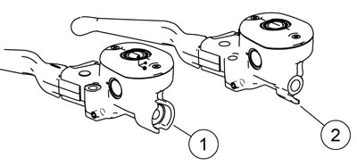
Figure 2-123. Front brake master cylinder identification: 1. XR 1200X; 2. XL models
1. Route the brake line. See 2.16 BRAKE LINES, Front Brake Line Routing.
2. See Figure 2-124 or Figure 2-125. Loosely install the master cylinder banjo bolt (2) and fitting with new sealing washers (1).
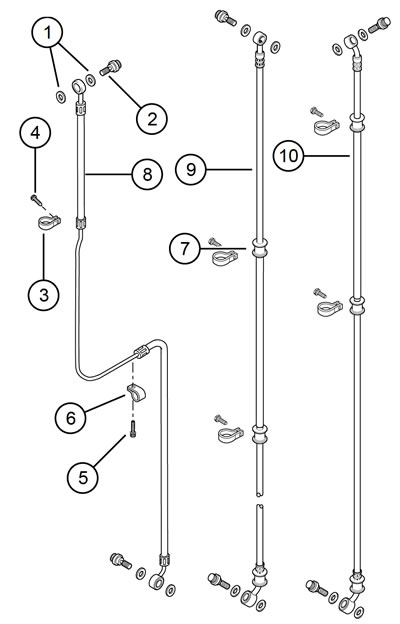
Figure 2-124. Brakelines: single disc models: 1. Sealing washer; 2. Banjo bolt; 3. Clamp; 4. Screw; 5. Screw w/captive washer; 6. Clamp; 7. Grommet; 8. Brakeline: XL 883L/N, XL 1200C/C ANV/X, XL 1200CP w/Pull Back; 9. Brakeline: XL 1200V/CP/CB w/Mini-Ape; 10. Brakeline: XL 1200CP/CA w/Drag Bar
3. Loosely install the upper clamp (3) with the screw (4):
- a. XL Models: To the upper fork bracket.
- b. XR 1200X: To the lower fork bracket.
4. Loosely install the lower clamp.
- a. Single Disc Models: To the lower fork bracket stem with screw with captive washer.
- b. Dual Disc Models: See Figure 2-125. Thread the screw (5) with captive washer through the brake line manifold (7) and guide (6) into the steering head stem.
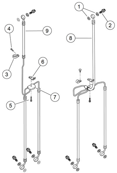
Figure 2-125. Brakelines: dual disc models: 1. Sealing washer; 2. Banjo bolt; 3. Clamp; 4. Screw; 5. Screw; 6. Guide; 7. Brakeline manifold; 8. Brakeline: XR 1200X; 9. Brakeline: XL 883R
5. Loosely install the banjo bolt and banjo fitting with new sealing washers to the brake caliper(s).
6. Tighten the fasteners to specification:
- a. Master cylinder banjo bolt to 20-25 ft·lbs (27.1-33.9 Nm)
- b. Clamp-to-fork bracket to 45-65 in·lbs (5.1-7.4 Nm)
- c. XL Models: brake line-to-steering stem clamp screw to 120-168 in·lbs (13.6-19.0 Nm)
- d. XR 1200X: brake line-to-steering stem clamp screw 96-144 in·lbs (11-16 Nm)
- e. Banjo bolt-to-brake caliper(s) to 20-25 ft·lbs (27.1-33.9 Nm)
7. Fill and bleed brakes with new DOT 4 BRAKE FLUID. See 2.17 BLEEDING BRAKES, Procedure.
Warning! After repairing the brake system, test brakes at low speed. If brakes are not operating properly, testing at high speeds can cause loss of control, which could result in death or serious injury.
8. Test ride motorcycle. Repeat brake bleeding, if necessary.
Front brake line routing
Warning! Do not bend metal brake line. Bending brake line could cause metal fatigue and brake failure, which could result in death or serious injury.
XL 883R
1. Fit the upper clamp to the metal fitting at the top of the single metal tube section.
Note. The brake line on dual disc models self-aligns. It creates a gap between the metal tubing section and the lower fork bracket. Visually confirm the gap.
2. Route the brake line behind the handlebar and the fork brackets.
3. Separate the two brake lines and route down to the calipers.
XL 883L/N, XL 1200X, XL 1200C/C ANV/CP w/pull back
1. See Figure 2-126. Fit the upper and lower clamps to the metal fittings at the ends of the metal tube section.
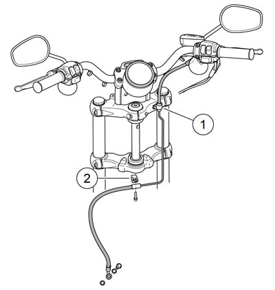
Figure 2-126. Brakeline Routing: XL 883L/N, XL 1200X, XL 1200C/C ANV/CP w/Pull Back: 1. Upper P-clamp; 2. Lower P-clamp
2. Route the brake line downward in front of the right side of the handlebar and inward behind fork brackets.
3. Continue routing the brake line downward crossing to left side of the vehicle under front fork lower bracket to the brake caliper.
4. Single Disc Models: See Figure 2-127. Adjust the location of the brake line in the lower P-clamp until there is a 1/4 in (6.35 mm) gap between the brake line metal tubing and the lower fork bracket pinch bolt.
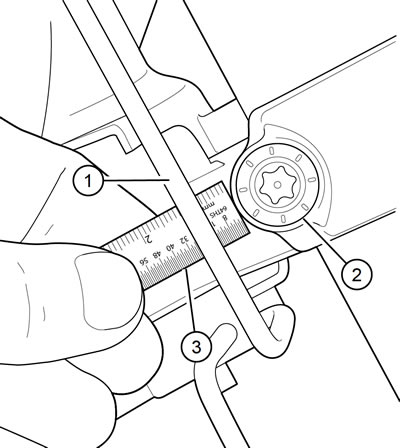
Figure 2-127. Measuring front brake line clearance: 1. Front brake line; 2. Lower fork bracket pinch bolt; 3. Ruler
XL 1200V/CP/CB w/mini-ape
1. Fit the upper and lower clamps to the brake line grommets.
2. See Figure 2-128. Match the straight banjo bolt fitting to the master cylinder and route the brake line over the top of the mini-ape and behind the fork brackets.
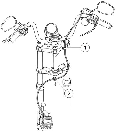
Figure 2-128. Brake line routing: XL 1200V/CP/CB w/mini-ape: 1. Upper P-clamp; 2. Lower P-clamp
3. Cross the brake line under the lower fork bracket and down the fork leg to the brake caliper.
XL 1200CP/CA with drag bar
1. See Figure 2-129. Fit the upper and lower clamps to the brake line grommets.

Figure 2-129. Brake line routing: XL 1200CP/CA w/drag bar: 1. Upper P-clamp; 2. Lower P-clamp
2. Match the banjo bolt fitting to the master cylinder and route the brake line behind the fork brackets.
3. Cross the brake line under the lower fork bracket and down the fork leg to the brake caliper.
XR1200X
1. See Figure 2-130. Fit the upper clamp to the metal fitting at the top of the single metal tube section.
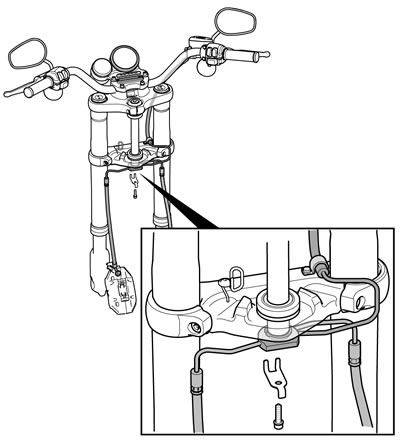
Figure 2-130. Brakeline routing: XR 1200X
Note. The brake line on dual disc models will self-align. It creates a gap between the metal tubing section and the lower fork bracket. Visually confirm the gap.
2. Route the brake line behind the handlebar and the fork brackets.
3. Separate the two brake lines and route down to the calipers.
Rear brake line: XL models
| FASTENER | TORQUE VALUE | |
| Stop lamp, rear, switch: XL Models | 132-168 in·lbs | 14.9-18.9 Nm |
| Brake line/switch, rear, tee bracket screw: XL Models | 72-120 in·lbs | 8.14-13.6 Nm |
| Brake hose clamp to battery tray screw | 30-40 in·lbs | 3.4-4.5 Nm |
| Brake hose clamp to rear fork screw | 30-40 in·lbs | 3.4-4.5 Nm |
| Brake line banjo bolt | 20-25 ft·lbs | 27.1-33.9 Nm |
| Brake caliper bleeder valve | 35-61 in·lbs | 4.0-6.9 Nm |
Caution! Direct contact of DOT 4 brake fluid with eyes can cause irritation. Avoid eye contact. In case of eye contact flush with large amounts of water and get medical attention. Swallowing large amounts of DOT 4 brake fluid can cause digestive discomfort. If swallowed, obtain medical attention. Use in well ventilated area. KEEP OUT OF REACH OF CHILDREN.
Notice: DOT 4 brake fluid will damage painted and body panel surfaces it comes in contact with. Always use caution and protect surfaces from spills whenever brake work is performed. Failure to comply can result in cosmetic damage.
Note. If DOT 4 brake fluid contacts painted surfaces, IMMEDIATELY flush area with clear water.
Removal
1. Drain rear brake master cylinder reservoir. See 2.13 REAR BRAKE MASTER CYLINDER RESERVOIR.
2. Drain the rear brake line:
- a. Remove bleeder nipple cap from bleeder valve on rear brake caliper.
- b. Install end of a length of 5/16 in (7.9 mm) ID clear plastic tubing over caliper bleeder valve. Place the free end in a suitable container.
- c. Open bleeder valve 1/2 turn.
- d. Pump brake pedal to drain brake fluid.
- e. Close bleeder valve.
3. See Figure 2-131. Unplug harness connectors [121] from stop lamp switch (7).
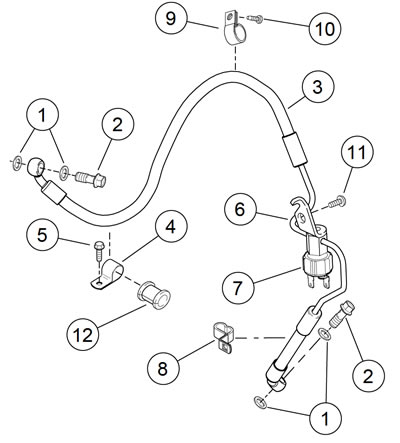
Figure 2-131. Rear brake line: XL models: 1. Washer (4); 2. Banjo bolt (2); 3. Rear brake line; 4. Clamp; 5. Screw; 6. Brake line/switch tee; 7. Stop lamp switch assembly; 8. Clamp; 9. Clamp; 10. Screw; 11. Screw; 12. Bushing X
4. Remove banjo bolt (2) and washers (1) to detach rear brake line (3) from master cylinder body and rear brake caliper. Discard washers.
5. Remove screw (5) to detach brake line clamp (4) with bushing (12) from rear fork.
6. Remove screw (10) to detach brake line clamp (9) from battery tray bracket.
7. Remove screw (11) securing brake line/switch tee (6) to battery tray bracket.
8. Feed brake line up through clamp (8).
9. Hold hex body of brake line/switch tee with an open-end wrench. Remove stop lamp switch from brake line/switch tee.
Installation
1. See Figure 2-131. Thread stop lamp switch (7) into brake line/switch tee (6) on new rear brake line (3). Hold hex body of brake line/switch tee with an open-end wrench. Tighten stop lamp switch to 132-168 in·lbs (14.9-18.9 Nm).
2. Feed rear brake line down through B-clamp (8).
3. Position brake line/switch tee mounting bracket on battery tray bracket. Secure with screw (11). Tighten to 72-120 in·lbs (8.14-13.6 Nm).
4. Install clamp (9) and screw (10) to secure rear brake hose to battery tray bracket. Tighten screw to 30-40 in·lbs (3.44.5 Nm).
Note. When installing clamp (4), bushing (12) and screw (5), adjust the brake hose length between rear caliper and clamp so there is no extra length. Do not twist or stretch brake hose. Make sure bushing sits squarely in clamp and around hose.
5. Install clamp (4) with bushing (12) and screw (5), to secure rear brake hose to rear fork. Tighten screw to 30-40 in·lbs (3.4-4.5 Nm).
Note. Master cylinder and brake caliper housings have a positive stop for banjo fitting. When tightening banjo bolt into master cylinder and brake caliper in the next step, rotate banjo fitting clockwise until it contacts positive stop.
6. Position new washers (1) on each side of banjo fittings by rear brake master cylinder and rear brake caliper. Insert banjo bolts (2) through washers and banjo fittings. Tighten to 20-25 ft·lbs (27.1-33.9 Nm).
Warning! After servicing brakes and before moving motorcycle, pump brakes to build brake system pressure. Insufficient pressure can adversely affect brake performance, which could result in death or serious injury.
Note. Rear brake master cylinder reservoir must be in a level position when filling and checking fluid level.
7. Position motorcycle upright (not resting on jiffy stand). Fill rear brake master cylinder reservoir with DOT 4 BRAKE FLUID and bleed brake system. See 2.17 BLEEDING BRAKES.
8. Tighten bleeder valve to 35-61 in·lbs (4.0-6.9 Nm). Install bleeder nipple cap.
Warning! Be sure that all lights and switches operate properly before operating motorcycle. Low visibility of rider can result in death or serious injury.
9. Verify tail lamp, and stop lamp.
10. Test ride motorcycle. If rear brake feels spongy, bleed system again. See 2.17 BLEEDING BRAKES.
Rear brake line: XR 1200X
| FASTENER | TORQUE VALUE | |
| Stop lamp, rear, switch: XR 1200X | 132-168 in·lbs | 14.9-18.9 Nm |
| Brake line/switch, rear, tee bracket screw: XR 1200X | 17-22 in·lbs | 1.9-2.5 Nm |
| Brake line banjo bolt | 20-25 ft·lbs | 27.1-33.9 Nm |
| Brake caliper bleeder valve | 35-61 in·lbs | 4.0-6.9 Nm |
Caution! Direct contact of DOT 4 brake fluid with eyes can cause irritation. Avoid eye contact. In case of eye contact flush with large amounts of water and get medical attention. Swallowing large amounts of DOT 4 brake fluid can cause digestive discomfort. If swallowed, obtain medical attention. Use in well ventilated area. KEEP OUT OF REACH OF CHILDREN.
Notice: DOT 4 brake fluid will damage painted and body panel surfaces it comes in contact with. Always use caution and protect surfaces from spills whenever brake work is performed. Failure to comply can result in cosmetic damage.
Note. If DOT 4 brake fluid contacts painted surfaces, IMMEDIATELY flush area with clear water.
Removal
1. Drain rear brake master cylinder reservoir. See 2.13 REAR BRAKE MASTER CYLINDER RESERVOIR.
2. Drain brake fluid:
- a. Remove cap from bleeder valve on rear brake caliper.
- b. Install a length of 5/16 in (7.9 mm) ID clear plastic tubing over caliper bleeder valve. Place free end in a suitable container.
- c. Open bleeder valve 1/2 turn.
- d. Pump brake pedal to drain brake fluid.
- e. Close bleeder valve.
3. See Figure 2-132. Unplug harness connectors [121] from stop lamp switch (2).
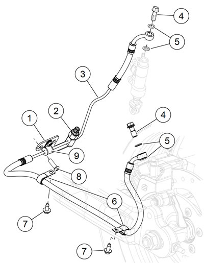
Figure 2-132. Rear brake line: XR 1200X: 1. Brake line bracket/switch tee; 2. Stop lamp switch assembly; 3. Rear brake line; 4. Banjo bolt (2); 5. Washer (4); 6. Clamp (2); 7. Fastener (2); 8. Fastener (2); 9. Clamp and bushing
4. Remove banjo bolts (4) and washers (5) to detach rear brake line (3) from master cylinder body and rear brake caliper. Discard washers.
5. Remove fasteners (7) to detach brake line clamps (6) from rear fork.
6. Remove fasteners (8) securing brake line bracket/switch tee (1) to lower frame.
7. Hold hex body of brake line bracket/switch tee with an open-end wrench. Remove stop lamp switch from brake line bracket/switch tee assembly.
8. If necessary, remove clamp and bushing (9).
Installation
1. See Figure 2-132. Thread stop lamp switch (2) into brake line bracket/switch tee (1) on rear brake line (3). Hold hex body of brake line bracket/switch tee with an open-end wrench. Using a 1.0-in six-point deep socket, tighten stop lamp switch assembly to 132-168 in·lbs (14.9-18.9 Nm).
2. If removed, install clamp and bushing (9).
Warning! Do not bend metal brake line. Bending brake line could cause metal fatigue and brake failure, which could result in death or serious injury.
3. Route brake line assembly to master cylinder and brake caliper. Loosely install new washers (5) and banjo bolts (4) to hold line in place.
4. Position brake line bracket/switch tee on lower frame and secure with fasteners (8). Tighten to 17-22 in·lbs (1.9-2.5 Nm).
5. Connect harness connectors [121] to stop lamp switch (2).
Notes:
- Make sure stop lamp switch harness does not contact grounding strap.
- Master cylinder and brake caliper housings have a positive stop for banjo fitting. When tightening banjo bolt into master cylinder and brake caliper in the next step, rotate banjo fitting clockwise until it contacts positive stop.
6. With new washers (5) on each side of banjo fittings, tighten banjo bolts (4) to 20-25 ft·lbs (27.1-33.9 Nm).
7. Secure brake line to bottom of rear fork with clamps (6) and fasteners (7).
Warning! After servicing brakes and before moving motorcycle, pump brakes to build brake system pressure. Insufficient pressure can adversely affect brake performance, which could result in death or serious injury.
Note. Rear brake master cylinder reservoir must be in a level position when filling and checking fluid level.
8. Position motorcycle upright (not resting on jiffy stand). Fill rear brake master cylinder reservoir with DOT 4 BRAKE FLUID and bleed brake system. See 2.17 BLEEDING BRAKES.
9. Tighten bleeder valve to 35-61 in·lbs (4.0-6.9 Nm). Install bleeder nipple cap.
10. Verify tail lamp, and stop lamp.
11. Test ride motorcycle. If rear brake feels spongy, bleed system again. See 2.17 BLEEDING BRAKES.
