
Removal
Note. Do not remove front brake calipers if only replacing brake pads See 1.17 BRAKE PADS AND DISCS: XR 1200X.
Caution! Direct contact of DOT 4 brake fluid with eyes can cause irritation. Avoid eye contact. In case of eye contact flush with large amounts of water and get medical attention. Swallowing large amounts of DOT 4 brake fluid can cause digestive discomfort. If swallowed, obtain medical attention. Use in well ventilated area. KEEP OUT OF REACH OF CHILDREN.
Note. Damaged banjo bolt surfaces will leak when reassembled. Prevent damage to seating surfaces by carefully removing brake line components.
Notice: DOT 4 brake fluid will damage painted and body panel surfaces it comes in contact with. Always use caution and protect surfaces from spills whenever brake work is performed. Failure to comply can result in cosmetic damage.
Note. If DOT 4 brake fluid contacts painted surfaces, IMMEDIATELY flush area with clear water.
1. See Figure 2-75. Remove bleeder nipple cap from bleeder valve (1) on front brake caliper.
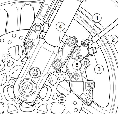
Figure 2-75. Front caliper assembly: XR 1200X: 1. Bleeder valve; 2. Banjo bolt (metric); 3. Sealing washer; 4. Mounting bolt (metric); 5. Banjo fitting
2. See Figure 2-76. Install end of a length of 5/16 in (7.9 mm) ID clear plastic tubing over caliper bleeder valve, while placing free end in a suitable container. Open bleeder valve about 1/2 turn. Pump brake hand lever repeatedly to drain brake fluid. Close bleeder valve.
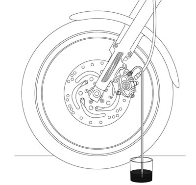
Figure 2-76. Bleeding hydraulic system
Note. Dispose of brake fluid in accordance with local regulations.
3. See Figure 2-75. Remove the banjo bolt (2) (metric) and both washers (3) to detach front brake line from caliper. Discard washers.
4. Remove both mounting bolts (4) (metric). Pull caliper assembly rearward to remove from brake disc.

Figure 2-77. Front brake caliper assembly: 1. Inner caliper housing; 2. Upper piston (large) (2); 3. Piston seal (large) (2); 4. Piston dust seal (large) (2); 5. Pad spring; 6. Crossover seal; 7. Outer caliper housing; 8. Bleeder valve; 9. Bleeder valve cap; 10. Caliper mounting bolt (2); 11. Bridge bolt (4); 12. Pad pin (2); 13. Pad set; 14. Piston dust seal (small) (2); 15. Piston seal (small) (2); 16. Lower piston (small) (2)
Disassembly
1. See Figure 2-78. Remove brake pad pins (1) and antirattle spring (2).
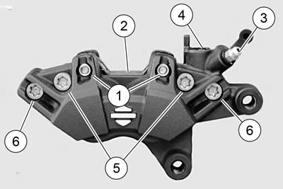
Figure 2-78. Preparing caliper for piston removal: 1. Pad pins (2) (metric); 2. Spring; 3. Bleeder valve; 4. Banjo bolt hole; 5. Bridge bolt, long (2); 6. Bridge bolt, short (2)
2. Slide one brake pad out of caliper assembly. Do not remove bleeder valve (3) at this time.
3. With one brake pad in the caliper, loosely install brake pad pins (1) to hold brake pad in place.
Warning! Compressed air can pierce the skin and flying debris from compressed air could cause serious eye injury. Wear safety glasses when working with compressed air. Never use your hand to check for air leaks or to determine air flow rates.
Note. Do not damage banjo bolt sealing surface or threads of banjo bolt hole in brake caliper. Use an air nozzle with a rubber tip.
Caution! When removing piston with compressed air, piston can develop considerable force and fly out of caliper bore. Keep hands away from piston to avoid possible injury.
4. See Figure 2-78. Gently apply low pressure compressed air to banjo bolt hole (4) to force pistons from caliper bores.
5. Remove brake pad pins and brake pad.
6. Remove bridge bolts (5, 6) and separate caliper housings.
7. Remove pistons from each housing by hand. If necessary, wiggle pistons gently to completely remove.
Note. Damaged piston bores will leak when reassembled. Do not use metal objects to remove or install objects from piston bores. Prevent damage to pistons, seals and bores by only using a wooden toothpick when servicing calipers.
8. See Figure 2-79. Using a wooden toothpick (1), remove dust seal (2) and piston seal (3) from each caliper bore. Discard seals.
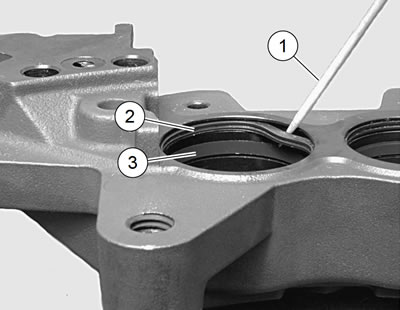
Figure 2-79. Caliper seals: 1. Wooden toothpick; 2. Dust seal; 3. Piston seal
9. See Figure 2-78. If necessary, remove bleeder valve (3).
Cleaning, inspection and repair
Warning! Use denatured alcohol to clean brake system components. Do not use mineral-based solvents (such as gasoline or paint thinner), which will deteriorate rubber parts even after assembly. Deterioration of these components can cause brake failure, which could result in death or serious injury.
1. Clean all rubber parts with DOT4 BRAKE FLUID. Do not contaminate with mineral oil or other solvents. Clean all metal parts with denatured alcohol. Wipe parts dry with a clean, lint-free cloth.
Warning! Compressed air can pierce the skin and flying debris from compressed air could cause serious eye injury. Wear safety glasses when working with compressed air. Never use your hand to check for air leaks or to determine air flow rates.
2. Blow out drilled passages and piston bore with low pressure compressed air from a clean air supply. Do not use a wire or similar instrument to clean drilled passages.
3. Carefully inspect all components. Replace as necessary.
- a. Check pistons for pitting, scratches or corrosion on outside surfaces.
- b. Inspect piston bores. Do not hone bores. Replace as necessary.
Note. The pad pins are manufactured with a relief near the center of their length, where the pad spring touches. Do not use this area as a measurement point to determine pad pin wear.
- c. Inspect pad pin for grooving and wear at the pad contact points. Measure the pad pin diameter in an unworn area and in an area of any grooving or wear. If wear exceeds 0.011 in (0.28 mm), replace pad pin.
- d. Inspect pad spring for wear or cracks. Replace if necessary.
- e. Always replace all seals after disassembly.
Warning! Always replace brake pads in complete sets for correct and safe brake operation. Improper brake operation could result in death or serious injury.
4. Inspect brake pads and brake disc. Replace if necessary.
- a. Specifications: See 1.17 BRAKE PADS AND DISCS: XR 1200X.
- b. Brake Disc: See 2.5 WHEELS.
Assembly
| FASTENER | TORQUE VALUE | |
| Brake caliper, front, bridge bolt | 12-18 ft·lbs | 16.9-24.5 Nm |
| Brake pad pin | 131-173 in·lbs | 14.8-19.6 Nm |
| Brake caliper bleeder valve | 35-61 in·lbs | 4.0-6.9 Nm |
1. Lubricate the following parts using a light coat of G40M BRAKE GREASE. All other surfaces must be dry.
- a. Nose radius of pistons.
- b. All surfaces of piston seals and dust seals.
Notes:
- Damaged piston bores will leak when reassembled. Do not use metal objects to remove or install objects in piston bores. Prevent damage to bores by only using a wooden toothpick when servicing calipers.
- Pistons and bores differ slightly in diameter: one large and one small in each housing.
2. See Figure 2-79. Install a new piston seal (3) and a new dust seal (2) into each piston bore.
3. See Figure 2-80. Carefully insert pistons (2, 3) by hand, nose radius first, into caliper bores. If installation shows resistance, remove piston(s) and check that seals are properly installed and fully seated in grooves. Press pistons completely into bores.

Figure 2-80. Caliper housings and pistons: 1. Crossover seal; 2. Large piston (2); 3. Small piston (2)
4. Install new crossover seal (1).
5. See Figure 2-78. Install bridge bolts (5, 6).
- a. Apply a drop of LOCTITE 569 THREAD SEALANT to the threads of the bridge bolts.
- b. Assemble caliper housings and secure with bridge bolts. Verify the bridge bolts are in the correct locations based on length.
- c. Tighten bridge bolts to 12-18 ft·lbs (16.9-24.5 Nm).
6. See Figure 2-81. Install brake pads and pad spring. Verify the spring is oriented as shown with the arrow and word "UP" (2) facing the banjo bolt hole (1). Secure with pad pins (3).
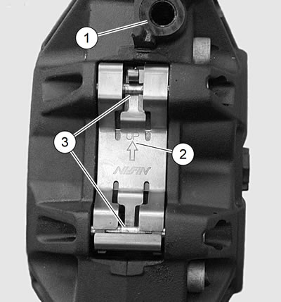
Figure 2-81. Front caliper pad spring orientation: 1. Banjo bolt hole; 2. Arrow and word "UP"; 3. Pad pins (2)
7. Tighten pad pins to 131-173 in·lbs (14.8-19.6 Nm).
8. Install bleeder valve on caliper housing if removed. Tighten bleeder valve to 35-61 in·lbs (4.0-6.9 Nm).
Installation
| FASTENER | TORQUE VALUE | |
| Axle, front, nut | 60-65 ft·lbs | 81-88 Nm |
| Axle, front, pinch screw: XR 1200X | 41-48 ft·lbs | 55.6-65.1 Nm |
| Brake caliper, front, mounting bolt | 28-38 ft·lbs | 38.0-51.6 Nm |
| Brake line banjo bolt | 20-25 ft·lbs | 27.1-33.9 Nm |
| Brake master cylinder, front, reservoir cover screws | 9-17 in·lbs | 1.0-2.0 Nm |
Caution! Direct contact of DOT 4 brake fluid with eyes can cause irritation. Avoid eye contact. In case of eye contact flush with large amounts of water and get medical attention. Swallowing large amounts of DOT 4 brake fluid can cause digestive discomfort. If swallowed, obtain medical attention. Use in well ventilated area. KEEP OUT OF REACH OF CHILDREN.
Notice: DOT 4 brake fluid will damage painted and body panel surfaces it comes in contact with. Always use caution and protect surfaces from spills whenever brake work is performed. Failure to comply can result in cosmetic damage.
Note. If DOT 4 BRAKE FLUID contacts painted surfaces, IMMEDIATELY flush area with clear water.
1. Align calipers to brake discs.
- a. Tighten axle nut to 60-65 ft·lbs (81-88 Nm).
- b. Loosen axle pinch screw nut.
- c. Position right fork leg against bearing spacer. Tighten axle pinch screw to 41-48 ft·lbs (55.6-65.1 Nm).
2. See Figure 2-82. Place brake caliper over brake disc with bleeder valve (1) facing upwards. Install mounting bolts (4) and tighten to 28-38 ft·lbs (38.0-51.6 Nm).

Figure 2-82. Front caliper assembly: XR 1200X: 1. Bleeder valve; 2. Banjo bolt (metric); 3. Sealing washer; 4. Mounting bolt (metric); 5. Banjo fitting
Notice: Avoid leakage. Be sure gaskets, banjo bolt(s), brake line and caliper bore are clean and undamaged before assembly.
Note. Brake caliper housing has a positive stop for banjo fitting. When tightening banjo bolt into brake caliper in the next step, rotate banjo fitting clockwise until it contacts positive stop.
3. Position a new washer (3) on each side of hydraulic brake line banjo fitting (5). Insert banjo bolt (2) through washers and fitting. Tighten to 20-25 ft·lbs (27.1-33.9 Nm).
4. Bleed brake system. See 2.17 BLEEDING BRAKES.
Note. Bleed both calipers.
Warning! A plugged or covered relief port can cause brake drag or lock-up, which could lead to loss of control, resulting in death or serious injury.
5. Verify operation of master cylinder relief port. With motorcycle positioned with master cylinder reservoir is level, squeeze brake lever slowly with reservoir cover removed. A slight spurt of fluid will break the surface if all internal components are working properly.
6. Install gasket and cover on master cylinder. Install screws. Tighten to 9-17 in·lbs (1.0-2.0 Nm).
Warning! After repairing the brake system, test brakes at low speed. If brakes are not operating properly, testing at high speeds can cause loss of control, which could result in death or serious injury.
7. Test brake system.
- a. Turn ignition switch ON. Squeeze brake hand lever to verify operation of the stop lamp.
- b. Test ride the motorcycle. If the brakes feel spongy, bleed the system again. See 2.17 BLEEDING BRAKES.
Note. Avoid making hard stops for the first 100 mi (160 km) to allow the new pads to become conditioned to the brake discs.