| PART NUMBER | TOOL NAME |
| HD-44060-C | WHEEL BEARING INSTALLER/REMOVER |
| FASTENER | TORQUE VALUE | |
| Single caliper cast front wheel hub plate screw | 16-24 ft·lbs | 21.7-32.6 Nm |
Inspection
1. Inspect the play of the wheel bearings by finger while they are in the wheel. Rotate the inner bearing race and check for abnormal noise. Make sure bearing rotates smoothly.
2. Check wheel bearings and axle spacers for wear and corrosion. Excessive play or roughness indicates worn bearings. Replace bearings in sets only.
Removal
1. If not already done, remove wheel from motorcycle. See 2.5 WHEELS. On models with a single front brake caliper, remove hub plate from wheel on side opposite front brake disc.
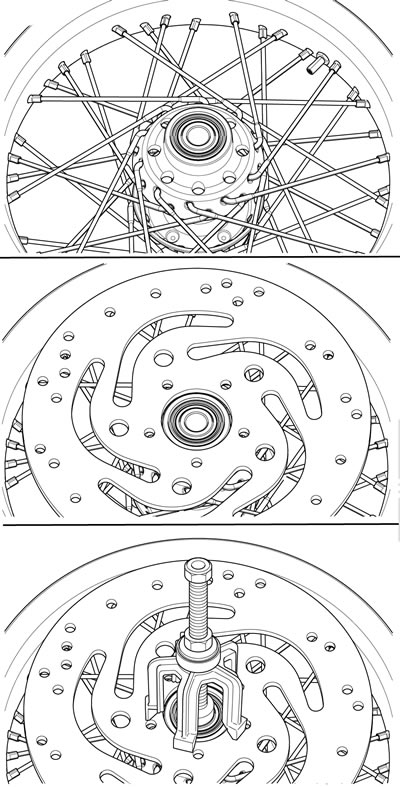
Note. See Figure 2-21. Some wheel hubs may not provide adequate support for the puller bridge. In these cases, center a used brake disc over the hub to support the puller bridge while removing the bearing.

Figure 2-21. Brake disk as puller aid
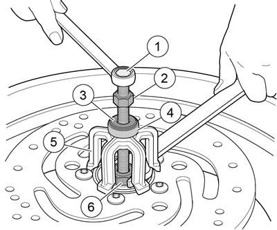
2. See Figure 2-22. Obtain WHEEL BEARING INSTALLER/REMOVER (Part No. HD-44060-C) and assemble.

Figure 2-22. Wheel bearing removal tool: 1. Forcing screw; 2. Nut; 3. Washer; 4. Bearing; 5. Bridge; 6. Collet with ball bearing inside
- a. Sparingly apply graphite lubricant to threads offorcing screw (1) for prolonged service life and smooth operation.
- b. Install nut (2), washer (3) and bearing (4) on screw. Insert assembly through hole in bridge (5).
- c. Drop ball bearing inside collet (6). Fasten collet and ball bearing to forcing screw.
3. Hold end of forcing screw and turn collet to expand edges of collet.
4. See Figure 2-23. When expanded collet has gripped bearing edges, hold end of forcing screw (1) and turn the nut (2) to remove bearing from wheel.

Figure 2-23. Removing bearing: 1. Forcing screw; 2. Nut
5. Remove spacer from inside wheel hub.
6. Repeat procedure for opposite side bearing. Discard both bearings upon removal.
Installation
Notes:
- When installing wheel bearings, use specialty tool WHEEL BEARING INSTALLER/REMOVER (Part No. HD-44060-C).
- Always install first bearing on primary brake disc side. If front wheel has two brake discs, install bearing on the left side first.
1. Obtain WHEEL BEARING INSTALLER/REMOVER (Part No. HD-44060-C) and assemble.
- a. Sparingly apply graphite lubricant to threads of threaded rod for prolonged service life and smooth operation.
- b. See Figure 2-24. Place threaded rod (1) through support plate (2). Insert assembly through wheel.
- c. See Figure 2-25. Place new bearing on rod (1) with lettered side facing out.
- d. Assemble installer (5), bearing (4), washer (3) and nut (2) over rod.

Figure 2-24. Assembling installation tool: 1. Threaded rod; 2. Support plate

Figure 2-25. Installing bearing: 1. Threaded rod; 2. Nut; 3. Washer; 4. Bearing; 5. Installer; 6. Wheel bearing
2. Hold hex end of threaded rod and turn nut to install wheel bearing. Bearing is fully seated when nut can no longer be turned. Remove tool.
3. Install spacer inside wheel hub.
4. Reverse tool and install opposite side wheel bearing.
5. Install hub plate opposite brake disc and secure with new screws. Tighten to 16-24 ft·lbs (21.7-32.6 Nm).
