
| FASTENER | TORQUE VALUE | |
| Hub plate mounting screw | 16-24 ft·lbs | 21.7-32.6 Nm |
| Brake disc, front, screw | 16-24 ft·lbs | 21.7-32.6 Nm |
| Brake disc, front, screw | 16-24 ft·lbs | 21.7-32.6 Nm |
| Brake disc, front, screw | 16-24 ft·lbs | 21.7-32.6 Nm |
| Brake disc, front, screw | 16-24 ft·lbs | 21.7-32.6 Nm |
| Axle, front, nut | 60-65 ft·lbs | 81-88 Nm |
| Axle, front, pinch screw: XL Models | 21-27 ft·lbs | 28.5-36.6 Nm |
| Axle, front, pinch screw: XR 1200X | 41-48 ft·lbs | 55.6-65.1 Nm |
Removal
1. Raise the front wheel off the ground.
Notes:
- Do not operate the front brake lever with the front wheel removed or the caliper pistons may be forced out. Seating the pistons requires disassembly of the caliper.
- On models with dual disc brakes, remove both calipers.
2. See Figure 2-10. Remove brake caliper mounting screws (3). Slide caliper (4) off brake disc and secure caliper out of the way.
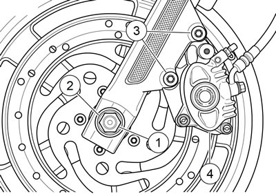
Figure 2-10. Left side front wheel mounting: 1. Axle nut; 2. Flat washer; 3. Brake caliper mounting screws; 4. Brake caliper
3. XL 1200X/C/C ANV/CP/CA/CB: Remove the front fender. See 2.31 FRONT FENDER.
4. Remove axle nut (1) and flat washer (2) from axle on left side of vehicle.
5. See Figure 2-11. On right side of vehicle, loosen nut (4) on pinch screw (1). Pull axle out of hub while supporting wheel.
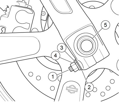
Figure 2-11. Right side front wheel mounting: 1. Pinch screw; 2. Washer; 3. Lockwasher; 4. Nut; 5. Axle
6. Remove spacer and front wheel assembly.
Disassembly: cast front wheel
1. If necessary, remove tire. See 2.4 TIRES.
2. Remove five screws and left side brake disc.
3. If necessary, remove five screws and right side brake disc (dual front disc models) or hub plate (single front disc models).
4. If necessary, remove roller bearings and hub spacer. See 2.5 WHEELS, Sealed Wheel Bearings.
Assembly cast single disc
Warning! Be sure that brake fluid or other lubricants do not contact brake pads or discs. Such contact can adversely affect braking ability, which could cause loss of control, resulting in death or serious injury.
1. See Figure 2-12. Install hub spacer (7) and new wheel bearings (6). See 2.5 WHEELS, Sealed Wheel Bearings.

Figure 2-12. Single disc wheels: XL models: 1. Axle; 2. Nut; 3. Washer; 4. Wide spacer; 5. Narrow spacer; 6. Bearings (2); 7. Hub spacer; 8. Hub plate: XL 883N; 9. Fastener (10); 10. Brake disc; 11. XL 883N; 12. XL 883L; 13. XL 1200C/C ANV/CP/CA
2. XL 883N: Install hub plate (8) on right side of wheel. Secure with new screws and tighten in an alternating pattern to 16-24 ft·lbs (21.7-32.6 Nm).
Note. See Figure 2-13. Orient brake discs with the word LEFT (1) facing out. Verify that the bulb shaped end (2) of the slots points opposite the direction of rotation (3).
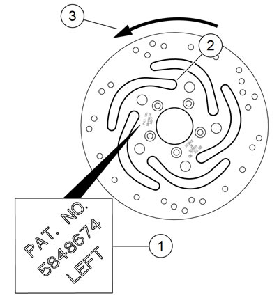
Figure 2-13. Single disc orientation: 1. Left; 2. Slot bulb end; 3. Direction of rotation
3. Install brake disc. Secure with new screws and tighten in an alternating pattern to 16-24 ft·lbs (21.7-32.6 Nm).
Assembly cast dual disc: XL 883R
1. See Figure 2-14. Install hub spacer (7) and new wheel bearings (6). See 2.5 WHEELS, Sealed Wheel Bearings.
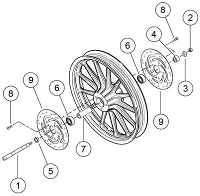
Figure 2-14. Dual disc wheel: XL 883R: 1. Axle; 2. Nut; 3. Washer; 4. Wide spacer; 5. Narrow spacer; 6. Bearing (2); 7. Hub spacer; 8. Fastener (10); 9. Brake disc (2)
Note. See Figure 2-15. The words LEFT (1) and RIGHT (2) on the discs will be located on the left and right sides.
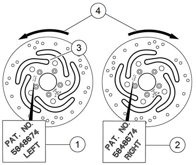
Figure 2-15. Dual disc orientation: XL 883R: 1. Left; 2. Right; 3. Slot bulb end; 4. Direction of rotation
2. Hold brake discs together with inboard sides facing each other (minimum thickness and part number stampings are on outboard side of brake disc). The bulb shaped end (3) of each slot is on the trailing edge of the slot in the direction of rotation (4).
3. Rotate one brake disc as necessary, until all vent holes are aligned with those of the other brake disc.
4. Keeping the paint marks on the edge of both discs aligned, install both brake discs onto hub. Secure with new screws.
5. Holding brake discs aligned, use a felt marking pen or paint pen to draw a line across the edge of both brake discs.
6. Tighten in an alternating pattern to 16-24 ft·lbs (21.7-32.6 Nm).
7. Verify that wheel is true. See 2.7 CHECKING AND TRUING WHEELS, Cast Wheel Runout.
Assembly cast dual disc: XR 1200X
See Figure 2-16. XR 1200X models are equipped with a floating front brake disc. They are non-directional and do not need to be matched with opposite disc.
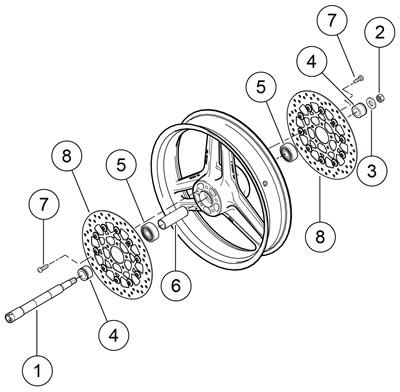
Figure 2-16. Dual disc wheel: XR 1200X: 1. Axle; 2. Nut; 3. Washer; 4. Spacer (2); 5. Bearing (2); 6. Hub spacer; 7. Fastener (10); 8. Brake disc (2)
Tighten in an alternating pattern to 16-24 ft·lbs (21.7-32.6 Nm).
Disassembly: laced front wheel
1. See Figure 2-17. If necessary, remove five screws (1) and brake disc (9).
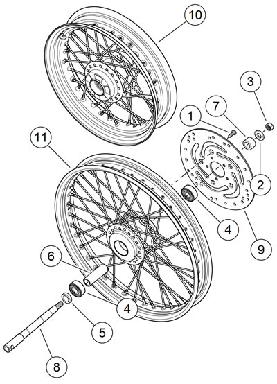
Figure 2-17. Laced front wheel: 1. Screw; 2. Washer; 3. Nut; 4. Roller bearing; 5. Bearing spacer, narrow; 6. Hub spacer; 7. Bearing spacer, wide; 8. Front axle; 9. Brake disc; 10. Wheel: 16 in XL 1200X/CP/CB certain markets; 11. Wheel: 21 in XL 1200V
2. If necessary, remove wheel bearings (4) and hub spacer (6). See 2.5 WHEELS, Sealed Wheel Bearings.
Note. If only rim is to be replaced, tape spokes together to hold position on hub and remove spokes from rim. Install taped hub/spoke assembly to new rim and tighten spokes. Then remove tape and true wheels. See 2.6 WHEEL LACING and 2.7 CHECKING AND TRUING WHEELS.
3. If it is necessary to disassemble wheel, loosen spoke nipples and spokes and slide each spoke out of hub.
Assembly: laced front wheel
1. See Figure 2-17. Install hub spacer (6) and new wheel bearings (4) if removed. See 2.5 WHEELS, Sealed Wheel Bearings.
2. If hub and rim were disassembled, reassemble and true wheel. See 2.6 WHEEL LACING and 2.7 CHECKING AND TRUING WHEELS.
Warning! Be sure that brake fluid or other lubricants do not contact brake pads or discs. Such contact can adversely affect braking ability, which could cause loss of control, resulting in death or serious injury.
3. Install brake disc (9). Secure with new screws (1) and tighten in an alternating pattern to 16-24 ft·lbs (21.7-32.6 Nm).
4. Verify that wheel is true.
Installation
1. Apply a light coat of ANTI-SEIZE LUBRICANT to the axle, bearing bores, and hub spacer bore.
2. Position wheel between forks. Verify that bearing spacers on right and left side of wheel bearings are in position.
3. With pinch screw loose, insert threaded end of axle through right side fork. Push axle through fork and wheel hub until it begins to emerge from left side of hub.
4. Push axle through left fork, until axle shoulder contacts external bearing spacer on right fork side.
5. Install flat washer and axle nut over threaded end of axle. Insert screwdriver or steel rod through hole in axle on right side of vehicle. While holding axle stationary, tighten axle nut to 60-65 ft·lbs (81-88 Nm).
6. Dual Disc Models: Align calipers to brake discs:
- a. Make sure axle pinch screw nut is loose.
- b. Position right fork leg against bearing spacer.
- c. XL Models: Tighten axle pinch screw to 21-27 ft·lbs (28.5-36.6 Nm).
- d. XR 1200X: Tighten axle pinch screw to 41-48 ft·lbs (55.6-65.1 Nm).
7. XL 1200X/C/C ANV/CP/CA/CB: Install front fender. See 2.31 FRONT FENDER.
8. Install brake caliper(s). See 2.9 FRONT BRAKE CALIPER: XL MODELS or 2.10 FRONT BRAKE CALIPER: XR 1200X.
Warning! Check wheel bearing end play after tightening axle nut to specified torque. Excessive end play can adversely affect stability and handling and can cause loss of control, which could result in death or serious injury.
Warning! Whenever a wheel is installed and before moving the motorcycle, pump brakes to build brake system pressure. Insufficient pressure can adversely affect brake performance, which could result in death or serious injury.
9. Pump brake lever to move pistons out until they contact outside brake pad. Verify piston location against pad.