| FASTENER | TORQUE VALUE | |
| Brake disc, rear, screw | 30-45 ft·lbs | 40.7-61.1 Nm |
| Sprocket mounting screw, 1st torque | 60 ft·lbs | 81.3 Nm |
| Sprocket mounting screw, final torque | 80 ft·lbs | 108.0 Nm |
| Shock absorber mounting bolt | 45-50 ft·lbs | 61-68 Nm |
| Axle, rear, nut | 95-105 ft·lbs | 129-142 Nm |
Removal
1. Secure motorcycle upright on a suitable lift. Raise rear end of motorcycle high enough to permit wheel removal.
2. XL Models: Remove rear muffler. See 4.13 EXHAUST SYSTEM: XL MODELS.
3. XL Models: Remove right lower shock absorber nut and pull screw out slightly. This will help avoid damage to sprocket when rear wheel is removed.
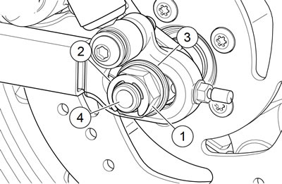
4. See Figure 2-18. Remove E-clip (2), axle nut (1) and washer (3).

Figure 2-18. Rear wheel mounting: 1. Axle nut; 2. E-clip; 3. Washer; 4. Rear axle
5. Loosen adjuster screws several turns to relieve belt tension.
6. Gently tap end of axle (4) with a soft hammer to loosen. Pull axle free of rear fork assembly.
7. Slide wheel forward and slip belt off sprocket.
Note. It is not necessary to disassemble rear brake caliper in order to remove rear wheel.
8. XR 1200X: Disengage brake hose from clamps on lower side of rear fork. Carefully slide caliper and bracket assembly forward to disengage from brake disk and boss on rear fork. Support assembly from frame using rope or bungee cord.
9. Remove spacers and roll rear wheel assembly back out of fork.
10. Remove rear wheel assembly.
Note. Do not operate rear brake pedal with rear wheel removed or caliper piston may be forced out of piston bore. Seating piston requires disassembly of caliper.
Disassembly
Notes:
- Sportster models sold in certain markets are equipped with rear wheel compensating sprockets. See C.1 COMPENSATING SPROCKET.
- Mark parts to indicate location. Do not mix parts upon assembly.
1. If necessary, remove tire. See 2.4 TIRES.
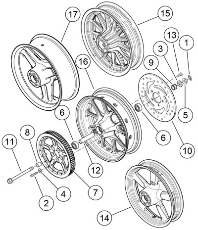
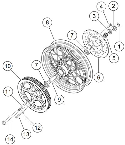
2. See Figure 2-19 or Figure 2-20. If necessary, remove screws to detach rear brake disc from left side of wheel.
3. If necessary, remove screws and washers to detach rear sprocket from right side of wheel.
4. If necessary, remove wheel bearings and hub spacer. See 2.5 WHEELS, Sealed Wheel Bearings.
Note. Laced Wheel: If only rim is to be replaced, tape spokes together to hold position on hub and remove spokes from rim. See 1.12 DRIVE BELT AND SPROCKETS.
5. Laced Wheel: If it is necessary to disassemble wheel, loosen the spoke nipples and spokes and slide each spoke out of hub.
Cleaning and inspection
1. Inspect all parts for damage or excessive wear.
Warning! Always replace brake pads in complete sets for correct and safe brake operation. Improper brake operation could result in death or serious injury.
2. Inspect brake pads and disc. See 1.16 BRAKE PADS AND DISCS: XL MODELS OR 1.17 BRAKE PADS AND DISCS: XR 1200X.
3. Inspect rear belt and sprocket. See 1.12 DRIVE BELT AND SPROCKETS.
Assembly
1. Laced Wheel: if wheel was disassembled, reassemble hub, rim, spokes and nipples, and tighten spokes. See 1.12 DRIVE BELT AND SPROCKETS.
2. Install hub spacer and new wheel bearings, if removed. See 2.5 WHEELS, Sealed Wheel Bearings.
- a. Cast or disc wheel: See Figure 2-19.
- b. Laced wheel: See Figure 2-20.

Figure 2-19. Cast rear wheel: 1. E-clip; 2. Screw (5); 3. Washer; 4. Washer (5); 5. Axle nut; 6. Roller bearing (2); 7. Sprocket; 8. Spacer, wide; 9. Spacer, narrow; 10. Brake disc; 11. Axle; 12. Hub spacer; 13. Screw (5); 14. Wheel: 16 in XL 1200C/C ANV/CP/CA (certain markets); 15. Wheel: 16 in XL 883N/R; 16. Wheel: 17 in XL 883L; 17. Wheel: 17 in XR 1200X

Figure 2-20. Laced rear wheel: 1. E-clip; 2. Axle nut; 3. Washer; 4. Fastener; 5. Spacer; 6. Brake disc; 7. Roller bearing (2); 8. Wheel: 16 in XL 1200X/V/CP/CB and XL 1200C/C ANV/CA certain markets; 9. Spacer, wide; 10. Sprocket; 11. Spacer, narrow; 12. Washer; 13. Fastener; 14. Axle
3. If brake disc was removed, install brake disc on valve stem side of wheel. Secure with new screws and tighten to 3045 ft·lbs (40.7-61.1 Nm).
Note. Sportster models sold in certain markets are equipped with rear wheel compensating sprockets. See C.1 COMPENSATING SPROCKET.
4. If rear sprocket was removed, install sprocket on side of wheel opposite valve stem.
- a. Secure with new screws and washers. Tighten to 60 ft·lbs (81.3 Nm).
- b. Loosen each screw 180 degrees and tighten to 80 ft·lbs (108.0 Nm).
5. Verify that wheel assembly is true. See 2.7 CHECKING AND TRUING WHEELS.
6. Install tire. See 2.4 TIRES.
Installation
1. See Figure 2-19 or Figure 2-20. Apply a light coat of ANTISEIZE LUBRICANT to the axle, bearing bores, and hub spacer bore.
2. Place wheel centrally in the rear fork assembly. Engage the brake disc in the caliper on XL models.
3. XR 1200X: With the wheel as far forward as possible, install the caliper/bracket assembly in place, engaging the brake disk and the boss on the rear fork.
4. Slide wheel forward and slip belt over sprocket and then slide the wheel back.
5. Position sprocket side spacer between wheel and rear fork.
6. Insert axle through right side of rear fork and right side axle adjuster, sprocket side spacer, wheel assembly, disc side spacer, rear caliper bracket, and left side of rear fork and left side axle adjuster.
7. Install washer and axle nut on left end of axle. Do not tighten nut at this time.
8. XL Models: Slide right lower shock absorber screw back in place. Install nut and tighten to 45-50 ft·lbs (61-68 Nm).
Note. If rear brake caliper was disassembled or removed, see 2.14 REAR BRAKE CALIPER: XL MODELS or 2.15 REAR BRAKE CALIPER: XR 1200X.
9. Check for proper belt tension and rear wheel alignment. See 1.24 WHEEL ALIGNMENT.
10. Tighten axle nut to 95-105 ft·lbs (129-142 Nm). Install Eclip.
Warning! Check wheel bearing end play after tightening axle nut to specified torque. Excessive end play can adversely affect stability and handling and can cause loss of control, which could result in death or serious injury.
11. Check wheel bearing end play. See 2.5 WHEELS, Wheel Bearing End Play.
12. XL Models: Install rear muffler. See 4.13 EXHAUST SYSTEM: XL MODELS.
Warning! Whenever a wheel is installed and before moving the motorcycle, pump brakes to build brake system pressure. Insufficient pressure can adversely affect brake performance, which could result in death or serious injury.
13. Pump brake pedal to move piston out until it contacts outside brake pad. Verify piston location against pad.
