
Note: The gearchange mechanism can be removed with the engine in the frame. If the engine has already been removed, ignore the preliminary steps.
Removal
1. Drain the engine oil (see Chapter 1).
2. Unscrew the gearchange lever pinch bolt and slide the lever off the shaft, noting the alignment of the punch mark on the shaft end 2 with either the slit in the clamp or the punch mark on the lever, depending on your model (see illustration). Unscrew the bolts securing the front sprocket cover and remove it, and on XL650V and XRV750 models the drive chain guide plate, noting how it fits (see illustration).
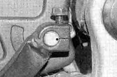
20.2a. Note the alignment of the punch mark, then unscrew the bolt and remove the lever

20.2b. Sprocket cover bolts (arrowed)
Wrap a single layer of thin insulating tape around the gearchange shaft splines to protect the oil seal lips as the shaft is removed.
3. Remove the clutch and the oil pump drive sprocket, chain and driven sprocket (see Section 18).
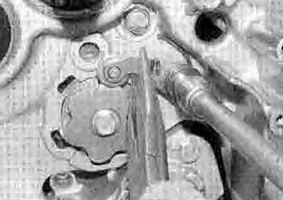
4. Unscrew the bolt securing the oil pipe (see illustration). Carefully pull the oil pipe out of its sockets, noting that an О-ring retains it at the bottom (see illustration). Discard the О-ring as a new one must be used. Unscrew the remaining bolts securing the transmission shaft bearing retainer plate and remove the plate, noting how it fits (see illustration).
20.4a. Unscrew the bolt...
20.4b ...and remove the oil pipe
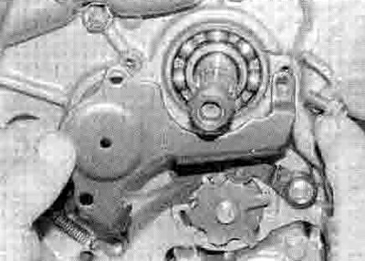
20.4c. Unscrew the remaining bolts and remove the retainer plate
5. Note how the gearchange selector arm claw locates onto the pins in the selector drum cam plate, and how the gearchange shaft centralising spring ends locate (see illustration 20.13c). Lift the selector arm claw off the selector drum and withdraw the gearchange shaft from the engine (see illustration).
20.5. Lift the arm off the drum and withdraw the shaft
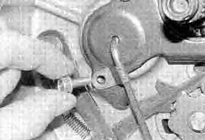
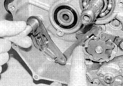
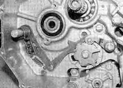
6. Note how the stopper arm spring ends locate and how the roller on the arm locates in the neutral detent on the selector drum cam, then unscrew the stopper arm bolt and remove the washer, the arm. the spring and the collar, noting how they fit (see illustration).

20.6. Note how the roller (A) and the spring ends (B) locate, then unscrew the bolt (C) and remove the arm. Cam plate bolt (D)
7. If necessary, unscrew the bolt securing the cam plate to the selector drum and remove it, noting that there is a locating dowel that fits between them - it is advisable to place some rag in the bottom of the crankcase to catch the dowel should it drop out (see illustration 20.6). Otherwise remove the dowel for safekeeping if it is loose. Also note the pins between the cam and the base plate and remove them if they are loose.
Inspection
8. Inspect the selector arm and the stopper arm return springs and the shaft centralising spring (see illustrations). If they are fatigued, worn or damaged they must be replaced with new ones. Also check that the centralising spring locating pin in the crankcase is securely tightened. If It is loose, remove it and apply a non-permanent thread locking compound to its threads, then tighten it securely.

20.8a. Check the selector arm assembly...

20.8b ...and the stopper arm assembly as described
9. Check the gearchange shaft for straightness and damage to the splines. If the shaft is bent you can attempt to straighten it, but if the splines are damaged the shaft must be replaced with a new one. Also check the condition of the shaft oil seal in the left-hand side of the crankcase. If it is damaged, deteriorated or shows signs of leakage it must be replaced with a new one. Where fitted, unscrew the bolt(s) securing the seal retainer plate and remove the plate, noting how it fits (see illustration 23.3). Lever out the old seal with a screwdriver (see illustration). Press or drive the new seal squarely into place, with its lip facing inward, using a seal driver or suitable socket (see illustration). Fit the retainer plate where removed and tighten its bolt(s) securely.
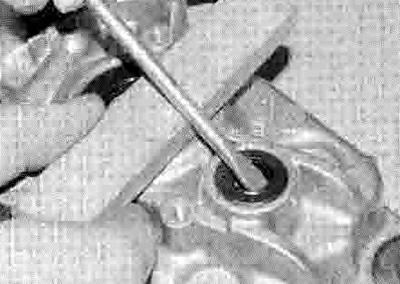
20.9a. Lever out the old seal...
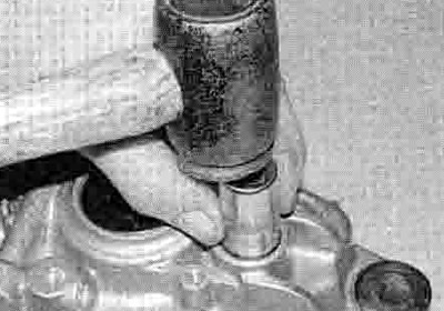
20.9b ...and press or drive the new one into place
10. Inspect the selector arm claw and the pins, and the stopper arm roller and the cam detents. If they are worn or damaged they must be replaced with new ones.
Installation
11. If removed, fit the pins into the cam base plate and push them through to the cam. Fit the locating dowel into the end of the selector drum. Install the cam plate, making sure the hole in the back of the base plate locates correctly on the dowel. Apply a suitable thread locking compound to the threads of the cam bolt and tighten it to the torque setting specified at the beginning of the Chapter.
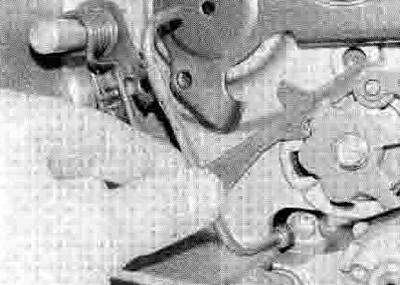
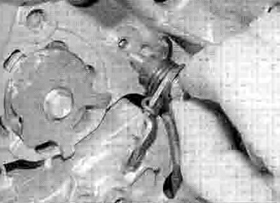
12. Fit the stopper arm bolt with its washer through the stopper arm, the return spring and the collar, then apply a threadlock to the threads of the bolt (see illustration 20.8b), Install the assembly onto the crankcase, making sure the spring ends locate correctly over the stopper arm and against the crankcase, and partially tighten the bolt (see Illustration). Lift the stopper arm using a screwdriver against the crankcase as a lever or a pair of pliers, then fully tighten the bolt, locating the roller onto the neutral detent in the cam as they become aligned (see illustration). Tighten the bolt to the specified torque setting. Afterwards make sure the arm is free to move and is returned by the pressure of the spring.
20.12a. Locate the stopper arm assembly on the crankcase...
20.12b ...then position the arm on the cam and tighten the bolt
13. Slide the gearchange shaft assembly into Its hole in the engine, lifting the selector arm claw Into position on the selector drum pins (see illustrations). Ensure the centralising spring ends are correctly located on each side of the pins on the shaft and the crankcase (see illustration).

20.13a. Slide the shaft into the crankcase...

20.13b ...and locate the arm onto the drum
20.13c. The installed assembly should be as shown
14. Install the transmission shaft bearing retainer plate and secure it with the top bolts (see illustration 20.4c). Fit a new О-ring onto the oil pipe (see illustration). Locate the pipe in its sockets, pressing the bottom in until the О-ring is felt to locate (see illustration 20.4b). Secure the pipe with the retainer plate bottom bolt (see illustration 20.4a).
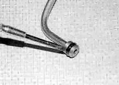
20.14. Fit a new О-ring onto the oil pipe
15. On XL650V and XRV750 models fit the drive chain guide plate. Install the front sprocket cover and tighten its bolts (see illustration 20.2b). Slide the gearchange lever onto the shaft, aligning the punch mark on the shaft end with that on the lever where there is one, or with the slit in the clamp if not (see illustration 20.2a). Tighten the pinch bolt and check that the gearchange mechanism works correctly.
16. Install oil pump drive chain and sprockets and the clutch (see Section 18).
17. Replenish the engine with oil (see Chapter 1).