
Note: To access the selector drum and forks the engine must be removed from the frame and the crankcases separated.
Removal
XL600V-H to R (1987 to 1995) models
1. Separate the crankcase halves (Section 23). Remove the crankshaft (see Section 27) - though not essential, working with it in place restricts access and makes the procedure fiddly.
2. The selector drum and forks must be removed along with the transmission shafts as a complete assembly. Note that each selector fork is marked for identification. The left-hand fork is marked with an 'L', the middle fork is marked with a 'C', and the righthand fork is marked with an 'R', all of which must face the right-hand crankcase half (see illustration 29.7). If no letters are visible, mark them yourself using a felt pen. The right and left-hand forks fit into the output shaft and the centre fork fits into the Input shaft. At this point make a careful note of where each transmission shaft is positioned in relation to the selector drum and the fork assembly - the assembly must be removed an installed as one, and it is easy to get confused when assembling them together on the work bench before installation.
3. Grasp the input shaft and output shaft and the selector drum and forks and withdraw them from the crankcase as an assembly, noting their relative positions and how they fit together. Separate the selector drum, forks and transmission shafts, noting how the guide pin on each fork locates in Its groove In the drum, and how each fork engages in the groove of its pinion.
4. Check whether the thrust washer on the left-hand end of each shaft is on the shaft or in the crankcase (probably lying loose on the bearing). Fit the washer onto the end of each shaft as a reminder for installation. Also note the thrust washer on the right-hand end of the output shaft.
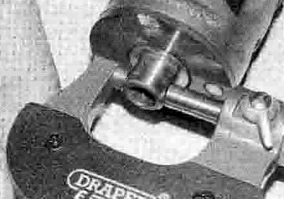
5. If required, slide the outer forks off the shaft, then bend back the tabs on the centre fork lockwasher, unscrew the bolt and remove the lockwasher, but note that unless you are performing the Inspection process (see below) it is best to keep the forks assembled on the shaft in their correct order and way round (see illustration).
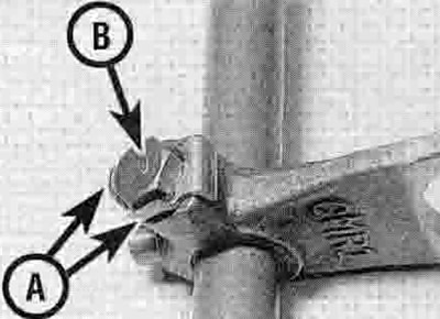
29.5. Bend back the lockwasher tabs (A) and remove the bolt (B)
All other models
6. Separate the crankcase halves (Section 23). Remove the crankshaft (see Section 27) - though not essential, working with it in place restricts access and makes the procedure fiddly.
7. Note that each selector fork is marked for identification. The left-hand fork is marked with an 'U', the middle fork is marked with a 'C', and the right-hand fork is marked with an 'R', all of which must face the right-hand crankcase half (see illustration). If no letters are visible, mark them yourself using a felt pen. The right and left-hand forks fit into the output shaft and the centre fork fits into the input shaft.
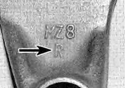
29.7. Note the identification letter on each fork (arrow)
8. Withdraw the selector fork shaft from the crankcase. Pivot each fork out of its track in the selector drum, then withdraw the selector drum from the crankcase (see illustration 29.26b). Remove the selector forks, noting how they locate in the groove in their pinion (see illustrations 29.5c, b and a). You may have to raise the bottom fork and its pinion so that the fork clears the crankcase land and can be removed. Once removed, slide the forks back onto the shaft in their correct order and way round.
Inspection
9. Inspect the selector forks for any signs of wear or damage, especially around the fork ends where they engage with the groove In the pinion. Check that each fork fits correctly in its pinion groove. Check closely to see if the forks are bent. If the forks are in any way damaged they must be replaced with new ones.
10. Measure the thickness of the fork ends and compare the readings to the Specifications (see illustration). Replace the forks with new ones if they are worn beyond their specifications.
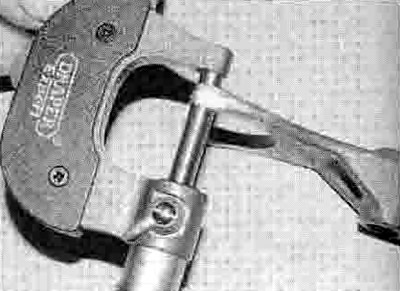
29.10. Measure the selector fork end thickness
11. Check that the forks fit correctly on their shaft. They should move freely with a light fit but no appreciable freeplay. Measure the internal diameter of the fork bores and the corresponding diameter of the fork shaft (see illustrations). Replace the forks and/or shaft with new ones if they are worn beyond their service limits. Check that the fork shaft holes in the casing are neither worn nor damaged.

29.11a. Measure the internal diameter of each fork bore...

29.11b ...and the external diameter of its location on the shaft
12. Check the selector fork shaft for trueness by rolling it along a flat surface. A bent rod will cause difficulty In selecting gears and make the gearshift action heavy. Replace the shaft with a new one if it Is bent.
13. Inspect the selector drum grooves and selector fork guide pins for signs of wear or damage. If either component shows signs of wear or damage the fork(s) and drum must be replaced with new ones.
14. Check that the selector drum bearing rotates freely and has no sign of freeplay between it and the casing (see illustration).
To fit a new bearing, remove the selector drum cam plate by unscrewing the bolt in its centre (see illustration). Note the locating pin in the end of the drum and remove it for safekeeping if required. Remove the old bearing and fit a new one. Install the selector drum cam. locating the pin in the cutout in the back of the cam plate. Apply a suitable non-permanent thread locking compound to the cam bolt and tighten it to the torque setting specified at the beginning of the Chapter.

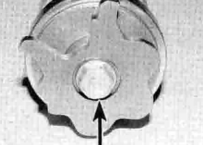
29.14a. Check the bearing (arrowed)
29.14b. Unscrew the bolt (arrowed) and remove the cam plate
15. On XL models, measure the diameter of the journal on the left-hand end of the drum and compare the measurement to the specifications (see illustration). If it is worn beyond the service limit, replace the selector drum with a new one. Also check the drum journal hole in the crankcase for wear or damage.
29.15. Measure the selector drum journal diameter
Installation
XL600V-H to R (1987 to 1995) models
16. Slide the middle selector fork marked 'C' onto the fork shaft so that the 'C' faces the right-hand end of the shaft. Install the lockwasher and bolt, then tighten the bolt securely and bend back the tabs of the lockwasher to secure it in place (see illustration 29.5).
17. Lubricate the selector fork shaft with molybdenum disulphide oil (a 50/50 mixture of molybdenum disulphide grease and clean engine oil). Slide the selector fork marked 'L' onto the left-hand end of the shaft so that the 'L' faces to the right-hand end. Slide the fork marked 'R' onto the right-hand end of the shaft so that the 'R' faces to the right-hand end.
18. The selector drum and forks must be installed along with the transmission shafts as a complete assembly. To achieve this without the entire assembly falling apart as it is installed, it is advisable to obtain some cable ties so the shafts and selector forks can be strapped together. Support the left-hand half of the crankcase on wooden blocks so the end of the transmission output shaft does not contact the work surface as it is installed.
19. Make sure that the thrust washer. Is installed on the left-hand end of each shaft -apply a smear of grease to the inner face of each washer to make them stick to their adjacent pinions and so prevent them dropping off as the shafts are installed (see illustrations 31.28b and 51d, and 30.17). Also make sure that the thrust washer is installed on the right-hand end of the output shaft (see illustration 31.55d).
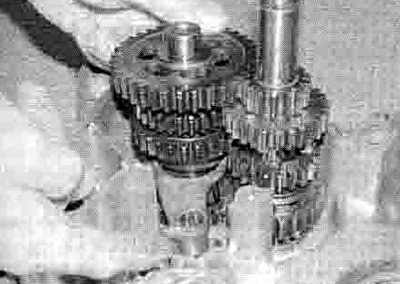
20. Lay the transmission input shaft and output shaft side by side on the bench so that the pinions for each gear mesh together (see illustration 30.18). Make sure that the shafts are the correct way round, with the smallest pinion on the input shaft meshing with the largest pinion on the output shaft.
21. Fit the selector fork assembly onto the transmission shafts, locating each fork into the groove in its pinion, and making sure their identification marks are positioned as described in Step 2. Also make sure that the fork assembly is positioned correctly in relation to each shaft as noted on removal.
22. Engage the selector drum with the forks, locating their guide pins in the selector drum tracks, again making sure everything is correctly positioned - the right-hand end of the selector drum carries the bearing, so the selector fork marked 'R' must be engaged in the groove nearest the bearing, and at the same end of the assembly as the smallest pinion on the input shaft and the largest pinion on the output shaft. If you intend to use cable ties to hold the assembly together, fit them now.
23. Grasp the input shaft and output shaft and the selector drum and forks and install them into the left-hand crankcase, making sure that both input shaft and output shaft ends engage in their bearings and the selector fork shaft end and the selector drum journal engage in their holes in the crankcase. Make sure the thrust washers do not drop off the ends of the shafts as they are installed. If cable ties were used, cut them and slip them out of position.
24. Install the crankshaft (see Section 27). Reassemble the crankcase halves (see Section 23).
All other models
25. Apply molybdenum disulphide oil (a 50/50 mixture of molybdenum disulphide grease and clean engine oil) to the selector fork ends. Install the selector fork marked 'L' first, with its letter facing up. and locate it in the groove of its pinion on the output shaft - you may have lift the pinion up the shaft a bit so that the fork clears the crankcase land (see illustration). Next install the fork marked 'C' into the groove of its pinion on the input shaft, again with the letter facing up (see illustration). Finally install the fork marked 'R'. letter facing up, into the groove of its pinion on the output shaft (see illustration). Position they forks so they will not get In the way of the selector drum when sliding it in.
29.25a. Locate the left-hand fork...

29.25b ...the centre fork...
29.25c ...and the right-hand fork in their pinions
26. Apply molybdenum disulphide oil (a 50/50 mixture of molybdenum disulphide grease and clean engine oil) to the journal on the lefthand end of the selector drum. Align the drum so that the neutral contact will be against the neutral switch and note the orientation of the cam in this position so that it can be returned to it later (see illustration). Slide the drum into position in the crankcase, making sure the journal locates in its bore in the casing (see illustration).
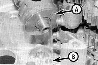
29.26a. Align the drum so the neutral contact (A) will be against the neutral switch (B)...

29.26b ...then locate it in the crankcase
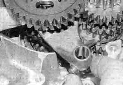
27. Locate the guide pin on the end of each fork into its groove in the selector drum - you may have to rotate the drum and/or move the forks and their pinions up to achieve this (see illustration). Lubricate the selector fork shaft with molybdenum disulphide oil (a 50/50 mixture of molybdenum disulphide grease and clean engine oil) and slide it through each fork in turn, and into its bore in the crankcase (see illustration 29.8a).

29.27. Pivot each fork so its guide pin locates in its track in the drum
28. Install the crankshaft (see Section 27). Reassemble the crankcase halves (see Section 23).
| XL models | Connecting rod code | |
| Crankpin journal code | 1 - (43.000 to 43.008 mm) | 2 - (43.008 to 43.016 mm) |
| A - (39.982 to 39.990 mm) | C - Brown | В - Black |
| В - (39.974 to 39.982 mm) | В - Black | A - Blue |
| XRV models | Connecting rod code | |
| Crankpin journal code | 1 - (46.000 to 46.008 mm) | 2 - (46.008 to 46.016 mm) |
| A - (42.982 to 42.990 mm) | F-Pink | E - Yellow |
| В - (42.974 to 42.982 mm) | E - Yellow | D - Green |