
Note: The clutch can be removed with the engine in the frame. If the engine has already been removed, ignore the preliminary steps which don't apply.
Removal
1. Drain the engine oil (see Chapter 1).
2. Remove the exhaust system (see Chapter 4).
3. On XL600V-H to К (1987 to 1989) models, unscrew the external oil pipe bolt from the clutch cover, and the pipe holder bolt (one of the cover bolts secures it). Discard the sealing washers as new ones must be used.
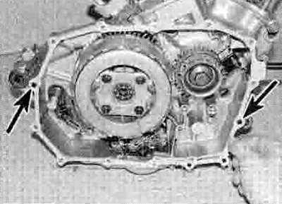
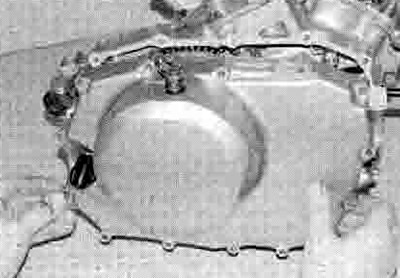
4. Working in a criss-cross pattern, slacken the clutch cover bolts, noting the clutch cable holder secured by one of the bolts (see illustration and 18.35c). Fully unscrew the cable holder bolt first and detach the cable end from the lever on the crankcase cover (see illustration 19.1c), Unscrew the remaining bolts and lift the cover away from the engine, being prepared to catch any residual oil. Note the release rod in the cover and remove it for safekeeping if required (see illustration 18.34).
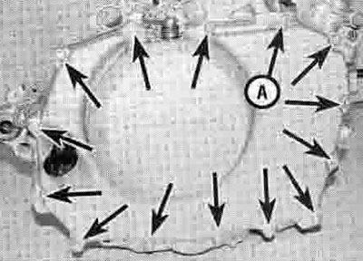
18.4. Clutch cover bolts (arrowed). Note the location of the cable bracket (A)
5. Remove the gasket and discard it. Note the positions of the two locating dowels fitted to the crankcase and remove them for safekeeping if they are loose (see illustration 18.35a). On XL600V-H, J and К (1987 to 1989) models, remove the oil orifice, noting which way round it fits, and discard its О-ring as a new one must be used.
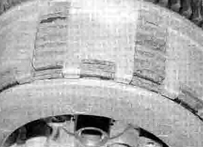
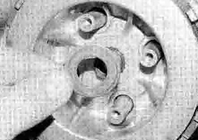
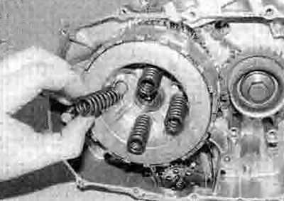
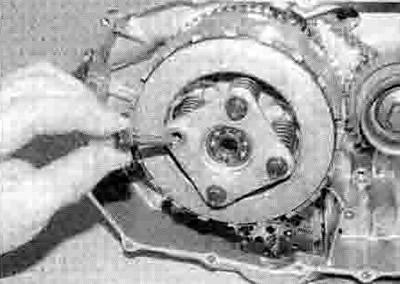
6. Working in a criss-cross pattern, gradually slacken the clutch release plate bolts until spring pressure is released, then remove the bolts, plate and springs (see illustrations).
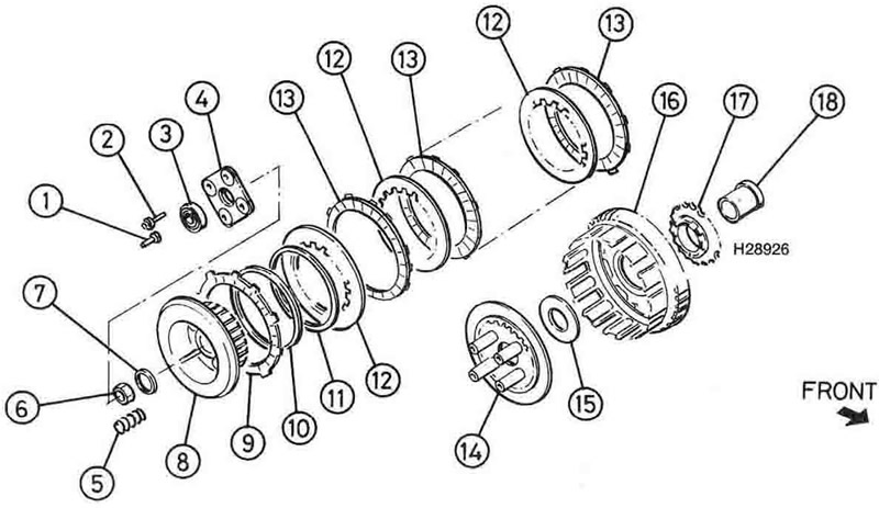
18.6a. Clutch assembly: 1. Release rod; 2. Release plate bolts; 3. Release bearing; 4. Release plate; 5. Springs; 6. Clutch nut; 7. Washer; 8. Clutch centre; 9. Friction plate-type. В; 10. Spring seat; 11. Anti-judder spring; 12. Plain plates; 13. Friction plates-type A; 14. Pressure plate; 15. Thrust washer; 16. Clutch housing; 17. Oil pump drive sprocket; 18. Clutch housing guid

18.6b. Unscrew the bolts (arrowed) and remove the plate and springs
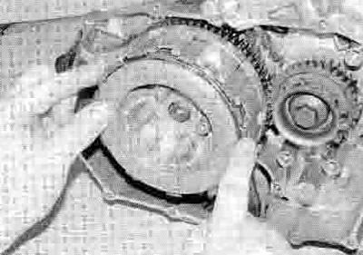
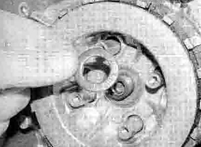
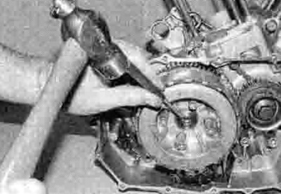
7. Unstake the clutch nut from the notch in the shaft (see illustration). To remove the clutch nut the transmission input shaft must be locked. This can be done in several ways. If the engine is in the frame, engage 5th gear and have an assistant hold the rear brake on hard with the rear tyre in firm contact with the ground. Alternatively, the Honda service tool (available from a dealer) can be used to stop the clutch centre from turning whilst the nut is slackened. If the engine has been removed from the frame (and the Honda tool is not available), a holding tool that bolts onto the rear sprocket (which can then be slipped onto the output shaft) can be easily made from two strips of steel bolted together. With the shaft locked, unscrew the clutch nut and remove the washer(s) - XL600V-V to X and XL650V models have a spring washer and a plain washer, all other models have a plain washer only (see illustration). Discard the nut as a new one must be used. Whilst the shaft is locked, and if you Intend removing it, also slacken the oil pump driven sprocket bolt (see illustration 18.12a).
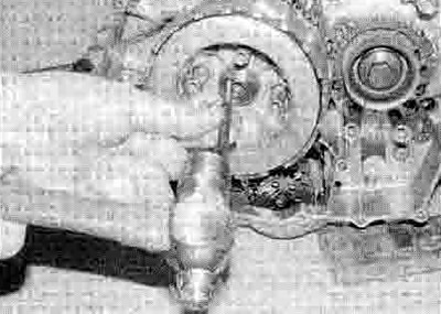
18.7a. Unstake the clutch nut...

18.7b ...then unscrew it as described in the text
A clutch centre holding tool can easily be made using two strips of steel bolted as shown, and with the ends drilled to accept bolts that can be threaded into the front sprocket. Thread a locknut up each bolt - these can then be tightened against the tool to secure the bolts after they have been threaded into the sprocket. Use an old sprocket if you have one.
8. Grasp the clutch centre with the complete set of clutch plates and the pressure plate and remove them as a pack (see illustration). Unless the plates are being replaced with new ones, keep them assembled in their original order on the clutch centre - positioning it upside down will prevent the plates slipping off. Otherwise, remove the pressure plate from the back of the clutch centre, then remove the friction and plain plates, noting how they fit. Finally remove the anti-judder spring and spring seat. Note that on XL models, there are two types of friction plate, identified as A and В (see illustration 18.6a). The outermost (type B) plate has a slightly larger internal diameter allowing it to fit over the anti-judder spring and spring seat, and its tangs fit into the shallow slots in the clutch housing. Take care not to mix them up. On XRV models all the friction plates are the same.
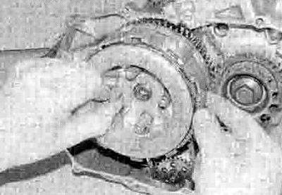
18.8. Remove the clutch centre and plates as an assembly
9. Remove the thrust washer from the shaft (see illustration 18.28).
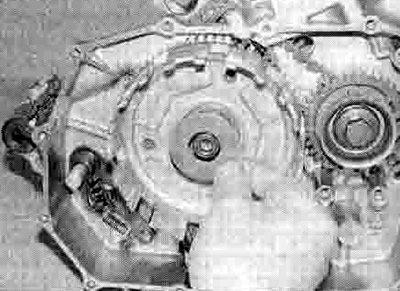
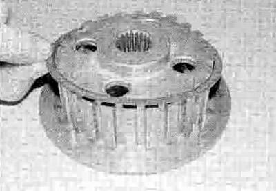
10. On XL models, slide the clutch housing off the shaft, noting that you may have to prevent the guide in the centre of the housing from sliding with it by pressing on its rim using a very small screwdriver (see illustration). If the guide slides with the housing, it brings the oil pump drive chain with it which could damage the chain.

18.10. Slide the clutch housing off the shaft
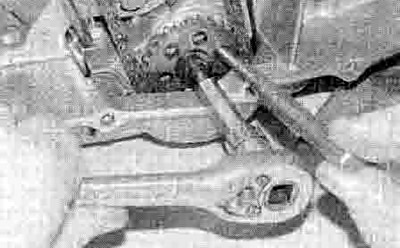
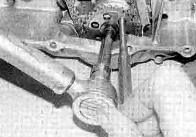
11. On XRV750 models, to remove the clutch housing it is necessary to align the primary drive sub-gear teeth with the mam gear teeth. To do this, first obtain a 6 mm bolt or rod to serve as a locking pin once the teeth are aligned. Locate a suitable screwdriver between the teeth and twist it to align them, then insert the bolt or rod through the holes in the gears (see illustration). Slide the clutch housing off the shaft (see illustration 18.10). Keep the bolt or pin located in the primary drive gear until the housing has been installed.

18.11. Align the gear teeth and insert a 6 mm bolt in the holes to lock them
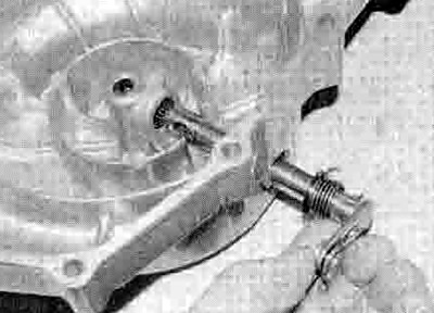
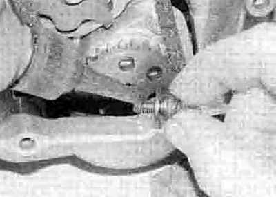
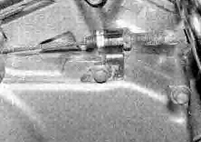
12 If required, unscrew the oil pump driven sprocket bolt and remove the driven sprocket, the chain and the drive sprocket (see illustration and 18.25d, b and a). If the bolt wasn't slackened earlier (see Step 7), lock the sprocket by locating a rod between the one of the holes and the crankcase as shown to prevent it from turning (see illustration). On XL models, note the 'IN' mark on the back of the oil pump driven sprocket which must face inwards; on XRV models note the 'OUT' mark on the back of the sprocket which must face outwards.

18.12a. Oil pump driven sprocket bolt (arrowed)
18.12b. Use a rod through the sprocket and located against the crankcase to prevent the sprocket turning
13. Remove the clutch housing guide from the input shaft (see illustration 18.24). On XL models, note how the tabs on the oil pump drive sprocket locate in the slots in the back of the clutch housing. On XRV models, note how the pins on the oil pump drive sprocket locate in the holes in the back of the clutch housing.
Inspection
14. After an extended period of service the clutch friction plates will wear and promote clutch slip. Measure the thickness of each friction plate using a Vernier caliper (see illustration). If any plate has worn to or beyond the service limit given in the Specifications at the beginning of the Chapter, the friction plates must be replaced as a set. Also, if any of the plates smell burnt or are glazed, they must be replaced as a set.

18.14. Measure the thickness of the friction plates
15. The plain plates should not show any signs of excess heating (bluing). Check for warpage using a flat surface and feeler gauges (see illustration). If any plate exceeds the maximum amount of warpage, or shows signs of bluing, all plain plates must be renewed as a set.
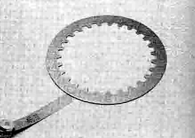
18.15. Check the plain plates for warpage
16. Measure the free length of each clutch spring using a Vernier caliper (see illustration 14.17a). If any spring is below the service limit specified, renew all the springs as a set. Also check the anti-judder spring and spring seat for damage or distortion and replace them with new ones if necessary.
17. Inspect the clutch assembly for burrs and indentations on the edges of the protruding tabs of the friction plates and/or slots in the edge of the housing with which they engage. Similarly check for wear between the inner tongues of the plain plates and the slots in the clutch centre. Wear of this nature will cause clutch drag and slow disengagement during gear changes as the plates will snag when the pressure plate is lifted. With care a small amount of wear can be corrected by dressing with a fine file, but if this is excessive the worn components should be renewed.
18. Using a Vernier caliper, measure the diameter of the output shaft where the clutch housing guide fits over it. Also measure the internal and external diameter of the housing guide and the internal diameter of the oil pump drive sprocket, and on XL600V models the internal diameter of the clutch housing where it fits over the guide. Compare the measurements to the Specifications at the beginning of the Chapter and replace any components that are worn beyond their service limit. Also check all the above components for signs of damage or scoring, and replace if necessary.
19. On XRV750 models, inspect the needle roller bearing in the clutch housing. If there are any signs of wear, pitting or other damage it must be renewed. The bearing is a press fit in the housing. When removing the old bearing, note carefully at what depth it sits in the centre and install the new bearing so that It sits in exactly the same place.
20. Check the pressure plate and thrust washer for signs of roughness, wear or damage, and replace any parts as necessary. Check the clutch release plate for signs of damage. Check that the bearing outer race is a good fit in the centre of the plate, and that the inner race rotates freely without any rough spots (see illustration). Renew the bearing if necessary.
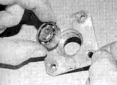
18.20. Check the release plate and bearing as described
21. Remove the release rod from the clutch cover (if not already done) (see illustration 18.34). Check the release mechanism for a smooth action If the action is stiff or rough, withdraw the shaft, noting the washer and how the return spring ends locate, then clean and check the oil seal and the two needle bearings in the cover, replacing them with new ones if necessary (see illustrations). The seal can be renewed by levering the old one out with a screwdriver and pressing the new one in. The needle bearings have to be drifted out. Lubricate the bearings and shaft before installing the shaft. Make sure the washer is on the shaft and the return spring ends locate correctly (see illustrations).
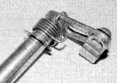
18.21a. Withdraw the shaft...
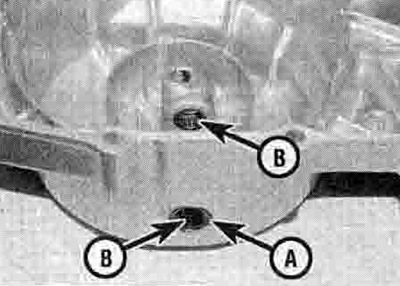
18.21b. and check the seal (A) and bearings (B)
18.21c. Make sure the washer and spring are correctly positioned ...

18.21d ...and the spring ends locate correctly
22. Check the teeth of the primary driven gear on the back of the clutch housing and the corresponding teeth of the primary drive gear on the crankshaft. Renew the clutch housing and/or primary drive gear if worn or chipped teeth are discovered (refer to Section 21 for the primary drive gear).
Installation
Note: If the primary drive gear has been removed and not yet installed, do so before installing the clutch (see Section 21).
23. Remove all traces of old gasket from the crankcase and clutch cover surfaces.
24. Smear the outside of the clutch housing guide with molybdenum disulphide oil (50% molybdenum grease and 50% engine oil), then slide the guide onto the input shaft (see illustration).
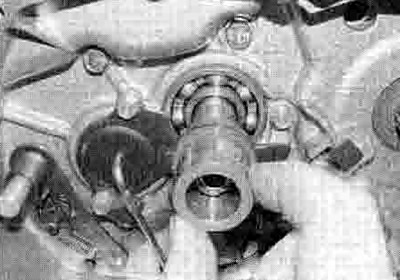
18.24. Slide the clutch housing guide onto the shaft...
25. Slide the oil pump drive sprocket onto the shaft, making sure the tabs or pins (according to model) face out, and slip the chain around the sprocket (see illustrations). Engage the driven sprocket with the chain, on XL models making sure the 'IN' mark faces inwards and on XRV models making sure the 'OUT' mark faces outwards, then locate the sprocket on the oil pump, aligning the flats between sprocket and shaft (see illustrations). Apply a suitable non-permanent thread locking compound to the sprocket bolt (see illustration). Fit the bolt with its washer and tighten it to the torque setting specified at the beginning of the chapter, locating a rod through one of the holes and against the crankcase to prevent the sprocket turning (see illustrations). Alternatively, tighten the bolt after tightening the clutch nut (see Step 32).

18.25a ...then fit the drive sprocket with its tabs or pins facing out
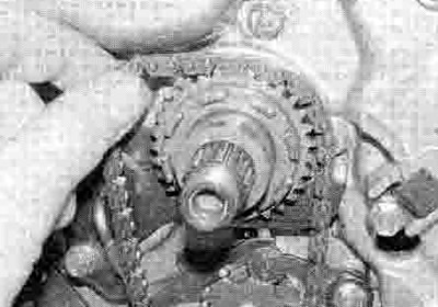
18.25b. Fit the chain around the sprocket...

18.25c ...then fit the driven sprocket into the chain, making sure it is the correct way round,...

18.25d ...and onto the shaft, aligning the flats
18.25e. Apply a locking compound to the bolt...
18.25f ...and tighten it to the specified torque, locking the sprocket as shown
26. On XRV models, make sure the bolt or rod is still located in the primary drive gear so that the sub-gear and main gear teeth are aligned. If the bolt or rod was removed, fit it as described in Step 11.
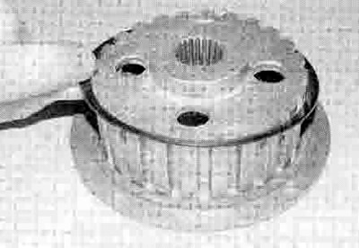
27. Slide the clutch housing onto the housing guide on the input shaft, making sure the tabs or pins on the oil pump drive sprocket engage with the slots or holes in the rear of the housing (turn the sprocket with your finger while pressing on the housing until the tabs/pins are felt to locate and the housing moves in a bit further, then double-check by making sure the sprocket can't turn independently of the housing), and the teeth of the primary driven gear engage with those of the primary drive gear (see illustrations).
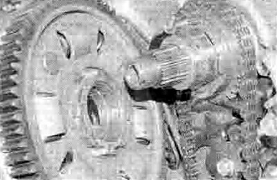
18.27a. The tabs or pins on the sprocket must engage with the slots or holes on the back of the clutch housing

18.27b. Slide the housing onto the guide, making sure it locates as described
28. Slide the thrust washer onto the shaft (see illustration).
18.28. Slide the thrust washer onto the shaft
29. Place the clutch centre face down on the bench. Fit the anti-judder spring seat onto the clutch centre, followed by the anti-judder spring; making sure the outer rim is raised off the spring seat as shown (see illustrations).
18.29a. Fit the spring seat...
18.29b ...and the spring...
18.29c ...making sure it is the correct way round
30. Coat each clutch plate with engine oil, then build up the plates in the housing, starting with a friction plate (the type В plate with the wider ID on XL models), then a plain plate, then alternating friction plates (type A on XL models) and plain plates until all are Installed (see illustrations). Align the friction plate tabs as shown to make installation into the clutch housing easier - the outermost friction plate tabs locate Into the shallow slots in the housing. Fit the pressure plate into the clutch centre, making sure it seats correctly with its protrusions locating in the slots in the centre (see illustration).

18.30a. Locate the first friction plate over the anti-judder spring...

18.30b ...then fit alternate plain plates...

18.30c ...and friction plates...

18.30d ...aligning them as shown

18.30e. Fit the pressure plate into the centre, making sure it locates correctly
31. Slide the clutch centre assembly onto the input shaft splines, feeding the friction plate tabs into the slots as you do. locating the outermost plate tabs into the shallow slots In the housing as shown (see illustrations).
18.31a. Slide the assembly onto the shaft...
18.31b ...locating the outer plate tabs into the shallow slots
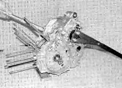
32. Fit the plain washer, and on XL600V-V to X and XL650V models the spring washer with the 'OUTSIDE' mark facing out, then fit a new clutch nut (see illustrations). Using the method employed on removal to lock the input shaft (see Step 7), tighten the nut to the 2 torque setting specified at the beginning of the Chapter (see illustration). If you are using the home-made holding tool with the front sprocket, tilt the engine forward as shown so that the tool rests against the work surface and does not come up against the gearchange shaft. Stake the rim of the nut into the indent in the end of the input shaft using a suitable punch (see illustration). Whilst the clutch is locked, and if not already done (see Step 25). also tighten the oil pump driven sprocket bolt to the specified torque setting, having first applied a suitable non-permanent thread locking compound to its threads.
Note: Check that the clutch centre rotates freely after tightening the clutch nut.
18.32a. Fit the plain washer...
18.32b ...and where fitted the spring washer...

18.32c ...then fit the clutch nut...
18.32d ...and tighten it to the specified torque
18.32e. Stake the rim of the nut into the notch
33. Install the clutch springs, release plate and release plate bolts and tighten them evenly in a criss-cross sequence to the specified torque setting (see illustrations).
18.33a. Fit the springs...
18.33b ...and the release plate, then tighten the bolts as described in the text
34. If removed, fit the release rod into the clutch cover, aligning the shaft so that the rod fits correctly (see illustration).

18.34 Align the shaft and install the release rod
35. If removed, insert the dowels in the crankcase, then fit the new gasket, locating it over the dowels (see illustration). XL600V-H to К (1987 to 1989) models, fit a new O-ring onto the oil orifice, then install the orifice into the crankcase with its smaller diameter hole facing out. Install the crankcase cover, making sure it locates correctly over the dowels (see illustration). Install all the clutch cover bolts except the one that also secures the clutch cable holder, and on XL600V-H to К (1987 to 1989) models the external oil pipe holder, and tighten them finger-tight. Connect the clutch cable end to the release arm (see illustration 19.1c), then locate the holder on the cover and secure it with its bolt (see illustration). Tighten the cover bolts evenly in a criss-cross sequence to the specified torque setting.
18.35a. Locate the new gasket onto the dowels (arrowed)...
18.35b ...then install the cover
18.35c Clutch cable holder
36. On XL600V-H to К (1987 to 1989) models, install the external oil pipe lower bolt, using new sealing washers, and the pipe holder bolt, and tighten them to the specified torque settings.
37. Install the exhaust system (see Chapter 4).
38 Refill the engine with oil (see Chapter 1).
38. Check the clutch lever freeplay and adjust if necessary (see Chapter 1).