Input shaft disassembly
When disassembling the transmission shafts, place the parts on a long rod or thread a wire through them to keep them in order and facing the proper direction.
Note: When removing the circlips, do not expand the ends any further than is necessary as they are easily distorted. Also take care to keep them square as they twist easily. If in doubt about the condition of a circlip, replace it with a new one. It is advisable to use new ones as a matter of course.
XL600V models
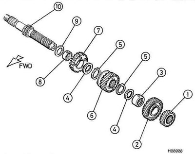
2. Remove the thrust washer from the left-hand end of the shaft, followed by the 2nd gear pinion (see illustration and 31.28b and a).

31.2 Transmission input shaft - XL600V: 1. Thrust washer; 2. 2nd gear pinion; 3. Circlip; 4. Splined washer; 5. 5th gear pinion; 6. 5th gear pinion bush; 7. 3rd gear pinton; 8. 4th gear pinion; 9. 4th gear pinion bush; 10. Input shaft with integral 1st gear pinion
3. Remove the circlip from the shaft (see illustration). Slide the splined washer and the 5th gear pinion off the shaft, followed by the 5th gear splined bush and splined washer (see illustrations 31.27d, c, b and a).

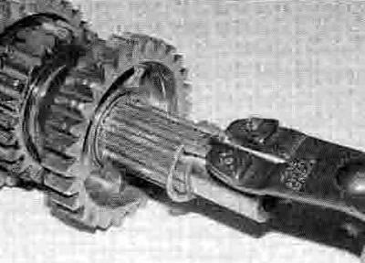
31.3. Carefully remove the circlip, taking care not to distort it
4. Remove the circlip securing the 3rd gear pinion, then slide the pinion off the shaft (see illustrations 31.26b and a).
5. Remove the circlip securing the 4th gear pinion, then slide the splined washer and the pinion off the shaft, followed by the 4th gear bush and the thrust washer (see illustrations 31.25e, d, c, b and a).
6. The 1st gear pinion is integral with the shaft.
XL650V models
7. Remove the thrust washer from the lefthand end of the shaft, followed by the 2nd gear pinion (see illustration).

31.7. Transmission input shaft - XL650V: 1. Thrust washer; 2. 2nd gear pinion; 3. 5th gear pinion; 4. 5th gear pinion bush; 5. Splined washer; 6. Circlip; 7. 4 th gear pinion; 8. 3rd gear pinion; 9. 3rd gear pinion bush; 10. Input shaft with integral 1st gear pinion
8. Slide the thrust washer off the shaft, followed by the 5th gear pinion, the 5th gear splined bush and the splined washer.
9. Remove the circlip securing the 4th gear pinion, then slide the pinion off the shaft.
10. Remove the circlip securing the 3rd gear pinion, then slide the splined washer and the pinion off the shaft, followed by the 3rd gear splined bush and the thrust washer.
11. The 1st geai pinion is integral with the shaft.
XRV750 models
12. Slide the 2nd gear pinion off the shaft, followed by the 5th gear pinion, the 5th gear splined bush and the splined washer (see illustration).

31.12. Transmission input shaft - XRV750 1. 2nd gear pinion; 2. 5th gear pinion; 3. 5th gear pinion bush; 4. Splined washer; 5. Circlip; 6. 4th gear pinion; 7. 3rd gear pinion; 8. 3rd gear pinion bush; 9. Thrust washer; 10. Input shaft with integral 1st gear pinion
13. Remove the circlip securing the 4th gear pinion, then slide the pinion off the shaft.
14. Remove the circlip securing the 3rd gear pinion, then slide the splined washer and the pinion off the shaft, followed by the 3rd gear splined bush and the thrust washer.
15. The 1st gear pinion is integral with the shaft.
Input shaft inspection
16. Wash all of the components In clean solvent and dry them off.
17. Check the gear teeth for cracking chipping, pitting and other obvious wear or damage. Any pinion that is damaged as such must be renewed.
18. Inspect the dogs and the dog holes in the gears for cracks, chips, and excessive wear especially in the form of rounded edges. Make sure mating gears engage properly. Renew the paired gears as a set if necessary.
19. Check for signs of scoring or blueing on the pinions, bushes and shaft. This could be caused by overheating due to inadequate ubrication. Check that all the oil holes and passages are clear. Renew any damaged pinions or bushes.
20. Check that each pinion moves freely on the shaft or bush but without undue freeplay. Check that each bush moves freely on the shaft but without undue freeplay. Measure the internal diameter of all gears which run on bushes and the external diameter of the bushes which they run on (see illustrations). If either component has worn to or beyond its service limit it must be replaced with a new one. Using the above measurements calculate the gear-to-bush clearance and compare the results to the specifications listed at the beginning of the Chapter. If the clearance exceeds the specified limit replace the relevant gear and bush as a pair. Also measure the internal diameters of the plain bushes and their corresponding shaft external diameter, and calculate the shaft-to-bush clearance (see illustrations). The Specifications at the beginning of the Chapter list which components need to be measured.

31.20a. Measure the internal diameter of the gear...

31.20b ...and the external diameter of its bush

31.20c. Measure the internal diameter of the bush...

31.20d ...and the external diameter of the shaft
21. The shaft is unlikely to sustain damage unless the engine has seized, placing an unusually high loading on the transmission, or the machine has covered a very high mileage. Check the surface of the shaft, especially where a pinion turns on it. and replace the shaft if it has scored or picked up, or if there are any cracks. Place the shah on V-blocks and check the runout at the shaft centre using a dial gauge. Damage of any kind can only be cured by replacement.
22. Check the bearings for play or roughness, and that they are a tight fit in the crankcase (see illustration). Renew any bearing that is worn. Refer to Tools and Workshop Tips in the reference Section for more information on bearing checks and removal and installation methods. Apply clean engine oil to the bearings.

31.22. Check the transmission shaft bearings
23. Check the circlips and thrust washers and replace any that are bent or appear weakened or worn. It is a good idea to use new circlips as a matter of course.
Input shaft reassembly
XL600V models
24. During reassembly, apply molybdenum disulphide grease to the inside and outside of the bushes, and lubricate all the other components with engine oil. Make sure the oil holes in the shaft are aligned with those on the bush or pinion. When installing the circlips, do not expand the ends any further than is necessary. Install the stamped circlips and washers so that their chamfered side faces the pinion it secures (see illustration 31.2).
25. Slide the thrust washer, 4th gear pinion bush and 4th gear pinion, with its dogs facing away from the integral 1 st gear, onto the lefthand end of the shaft (see illustrations). Slide the splined washer onto the shaft and fit the circlip, making sure it locates correctly in its groove (see illustrations).

31.25a. Slide the thrust washer...

31.25b ...the 4th gear bush...

31.25c ...and the 4th gear pinion onto the shaft

31.25d. Slide on the splined washer...

31.25e ...then fit the circlip...

31.25f ...making sure it locates correctly
26. Slide the 3rd gear pinion onto the shaft with its selector fork groove facing away from the 4th gear pinion, and secure it with the circlip, making sure it locates correctly in its groove (see illustrations).

31.26a. Slide the 3rd gear pinion onto the shaft...

31.26b. then fit the circlip, making sure it locates in its groove
27. Slide the splined washer, the 5th gear pinion splined bush, the 5th geai pinion with its dogs facing the 3rd gear pinion, and the splined washer onto the shaft, then secure them in place with the circlip, making sure it locates correctly in its groove (see illustrations).

31.27a. Slide the splined washer...

31.27b ...the Sth gear splined bush...

31.27c ...the 5th gear pinion...

31.27d ...and the spline washer onto the shaft...

31.27e ...then fit the circlip

31.27f ...making sure it locates correctly
28. Slide the 2nd gear pinion onto the shaft, followed by the thrust washer (see illustrations).

31.28a. Slide the 2nd gear pinion onto the shaft...

31.28b ...then fit the thrust washer

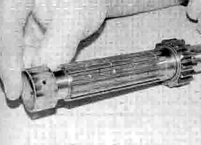
31.28c. The assembled input shaft should look like this
XL650V models
29. During reassembly, apply molybdenum disulphide grease to the inside and outside of the bushes, and lubricate all the other components with engine oil. Make sure the oil holes in the shaft are aligned with those on the bush or pinion. When installing the circlips, do not expand the ends any further than is necessary. Install the stamped circlips and washers so that their chamfered side faces the pinion it secures (see illustration 31.7).
30. Slide the thrust washer, 3rd gear pinion bush and 3rd gear pinion, with its dogs facing away from the integral 1st gear, onto the lefthand end of the shaft. Slide the splined washer onto the shaft and fit the circlip, making sure it locates correctly in its groove.
31. Slide the 4th gear pinion onto the shaft with its selector fork groove facing the 3rd gear pinion, and secure it with the circlip, making sure it locates correctly in its groove.
32. Slide the splined washer, the Sth gear pinion splined bush, the 5th gear pinion with its dogs facing the 3rd gear pinion, and the thrust washer onto the shaft.
33. Slide the 2nd gear pinion onto the shaft, followed by the thrust washer.
XRV750 models
34. During reassembly, apply molybdenum disulphide grease to the inside and outside of the bushes, and lubricate all the other components with engine oil. Make sure the oil holes in the shaft are aligned with those on the bush or pinion. When installing the circlips, do not expand the ends any further than is necessary. Install the stamped circlips and washers so that their chamfered side faces the pinion it secures (see illustration 31.12).
35. Slide the thrust washer, 3rd gear pinion bush and 3rd gear pinion, with its dogs facing away from the integral 1 st gear, onto the lefthand end of the shaft. Slide the splined washer onto the shaft and fit the circlip, making sure it locates correctly in its groove.
36. Slide the 4th gear pinion onto the shaft with its selector fork groove facing the 3rd gear pinion, and secure it with the circlip, making sure it locates correctly in its groove.
37. Slide the splined washer, the 5th gear splined bush, the 5th gear pinion with its dogs facing the 3rd gear pinion, and the 2nd gear pinion onto the shaft onto the shaft.
Output shaft disassembly
When disassembling the transmission shafts, place the parts on a long rod or thread a wire through them to keep them in order and facing the proper direction.
XL600V models
38. Remove the thrust washer from the righthand end of the shaft, then slide the 1st gear pinion, the 1st gear pinion bush and the thrust washer off the shaft (see illustration and 31.55d, c, b and a).

31.38 Transmission output shaft-XL600V: 1. Thrust washer; 2. 1st gear pinion; 3. 1st gear pinion bush; 4. 4th gear pinion; 5. Circlip; 6. Splined washer; 7. 3rd gear pinion; 8. 3rd gear pinion bush; 9. 2nd gear pinion bush; 10. 2nd gear pinion; 11. 5th gear pinion; 12. Output shaft
39. Slide the 4th gear pinion off the shaft (see illustration 31.54).
40. Remove the circlip securing the 3rd gear pinion, then slide the splined washer, the 3rd gear pinion, the 3rd gear pinion bush, and the thrust washer off the shaft (see illustration 31.53e, d, c, b and a).
41. Slide the 5th gear pinion off the wide section of the shaft (see illustration 31.52).
42. Remove the thrust washer from the lefthand end of the shaft, then slide the 2nd gear pinion, the 2nd gear pinion bush, and the thrust washer off the shaft (see illustrations 31.51d, c, b and a).
XL650V and XRV750 models
43. Slide the thrust washer off the shaft, followed by the 1st gear pinion, the 1st gear pinion bush, and the splined washer (see illustration overleaf).

31.43. Transmission output shaft - XL650V and XRV750: 1. Thrust washer; 2. 1 st gear pinion; 3. 1 st gear pinion bush; 4. Splined washer; 5. Circlip; 6. 3rd gear pinion; 7. 4th gear pinion; 8. 4th gear pinion bush; 9. Tabbed lockwasher; 10. Slotted splined washer; 11. 5th gear pinion; 12. 2nd gear pinion; 13. 2nd gear pinion bush; 14. Output shaft
44. Remove the circlip securing the 3rd gear pinion, then slide the pinion off the shaft.
45. Remove the circlip securing the 4th gear pinion, then slide the splined washer, the 4th gear pinion and the 4th gear pinion bush off the shaft.
46. Slide the tabbed lockwasher off the shaft, then turn the slotted splined washer to offset the splines and slide it off the shaft, noting how they fit together.
47. Slide the 5th gear pinion off the shaft.
48. Remove the circlip securing the 2nd gear pinion, then slide the splined washer, the pinion and its bush off the shaft.
Output shaft inspection
49. Refer to Steps 16 to 23 above.
Output shaft reassembly
XL600V models
50. During reassembly, apply molybdenum disulphide grease to the inside and outside ot the bushes, and lubricate all the other parts with engine oil. Make sure the oil holes in tho shaft are aligned with those on the bush or pinion. When installing the circlips, do not expand the ends any further than is necessary. Install the stamped circlips and washers so that their chamfered side faces the pinion It secures (see illustration 31.38).
51. Slide the thrust washer onto the left-hand end of the shaft, followed by the 2nd gear bush, the 2nd gear pinion and the thrust washer (see illustrations).

31.51a. Slide the thrust washer...

31.51b ...the 2nd gear bush...

31.51c ...the 2nd gear pinion...

31.51d ...and the thrust washer onto the shaft
52. From the right-hand end, slide the 5th gear pinion onto the wide section of the shaft with its selector fork groove facing away from the 2nd gear pinion (see illustration).

31.52. Slide the 5th gear pinion onto the wide section of the shaft
53. Slide the thrust washer onto the righthand end of the shaft, followed by the 3rd gear bush, the 3rd gear pinion with its dog holes facing out, and the splined washer, and secure them in place with the circlip, making sure it locates correctly in its groove (see illustrations).

31.53a. Slide the thrust washer...

31.53b ...the 3rd gear bush...

31.53c ...the 3rd gear pinion...

31.53d ...and the splined washer onto the shaft...

31.53e ...then fit the circlip

31.53f ...making sure it locates correctly
54. Slide the 4th gear pinion onto the shaft with its selector fork groove facing the 3rd gear pinion (see illustration).

31.54. Slide the 4th gear pinion onto the shaft
55. Slide the thrust washer onto the shaft, followed by the 1st gear pinion bush, the 1st gear pinion and the thrust washer (see illustrations).

31.55a. Slide the thrust washer...

31.55b .. the 1st gear pinion bush...

31.55c ...and the 1st gear pinion onto the shaft...

31.55d ...then fit the thrust washer
XL650V and XRV750 models
56. During reassembly, apply engine oil to the mating surfaces of the shaft, pinions and bushes. When installing the circlips, do not expand the ends any further than is necessary. Install the stamped circlips and washers so that their chamfered side faces the pinion it secures (see illustration 31.43).
57. Slide the 2nd gear pinion bush onto the shaft, followed by the 2nd gear pinion and the splined washer, then fit the circlip, making sure it locates correctly in its groove.
58. Slide the 5th gear pinion onto the shaft with Its selector fork groove facing away from the 2nd gear pinion.
59. Slide the slotted splined washer onto the shaft and locate it in its groove, then turn it in the groove so that the splines on the washer align with the splines on the shaft and secure the washer in the groove. Slide the lockwasher onto the shaft, so that the tabs on the lockwasher locate into the slots in the outer rim of the spline washer.
60. Slide the 4th gear pinion bush onto the shaft, followed by the 4th gear pinion with its dogs facing away from the 5th gear pinion, and the splined washer, then fit the circlip, making sure it locates correctly in its groove in the shaft.
61. Slide the 3rd gear pinion onto the shaft with its selector fork groove facing the 4th gear pinion, then fit the circlip, making sure it locates correctly in its groove.
62. Slide the splined washer onto the shaft, followed by the 1st gear pinion bush and the 1st gear pinion, then fit the thrust washer onto the end of the shaft.
