Check:
- 1. main and ignition fuses
- 2. battery
- 3. spark plugs
- 4. ignition spark gap
- 5. spark plug cap resistance
- 6. ignition coil resistance
- 7. pickup coil resistance
- 8. main switch
- 9. engine stop switch
- 10. neutral switch
- 11. sidestand switch
- 12. diode
- 13. starting circuit cut-off relay (diode)
- 14. wiring (of the entire ignition system)
Note: Before troubleshooting, remove the following part(-s):
- 1) battery cover
- 2) rider's seat
- 3) fuel tank
- 4) steering head side covers
- 5) tool box cover
- 6) left side cover
- 7) cylinder head covers
- Troubleshoot with the following special tool(-s).
- Ignition checker: 90890-06754
- Pocket tester: 90890-03112
1. Main and ignition fuses
Check the main and ignition fuses for continuity. Refer to "Checking the fuses". Are the main and ignition fuses OK?
NO: Replace the fuse(-s).
YES:
2. Battery
Check the condition of the battery. Refer to "Checking and charging the battery". Min. open-circuit voltage: 12.8 V or more at 20°C. Is the battery OK?
NO: Clean the battery terminals. Recharge or replace the battery.
YES:
3. Spark plugs
The following procedure applies to all of the spark plugs.
Check the condition of the spark plug.
Check the spark plug type.
Measure the spark plug gap. Refer to "Checking the spark plugs".
- Stand Standard spark plug: BPR7ES, W22EPR-U
- Spark plug gap: 0.7-0.8 mm
Is the spark plug in good condition, is it of the correct type, and its gap within specification?
NO: Re-gap or replace the spark plug.
YES:
4. Ignition spark gap
The following procedure applies to all of the spark plugs.
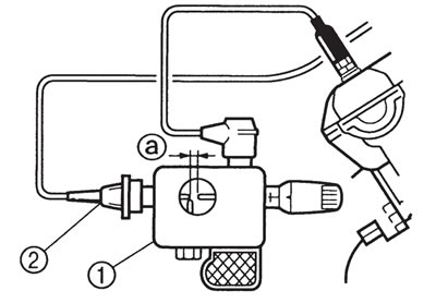
Disconnect the spark plug cap from the spark plug.
Connect the ignition checker (1) as shown.
(2) Spark plug cap
Set the main switch to "ON".
Measure the ignition spark gap (a).
Crank the engine by pushing the start switch and gradually increase the spark gap until a misfire occurs.

- Min. ignition spark gap: 6 mm
Is there a spark and is the spark gap within specification?
YES: The ignition system is OK.
NO:
5. Spark plug cap resistance
The following procedure applies to all of the spark plug caps.
Disconnect the spark plug cap from the spark plug.
Connect the pocket tester (Ω x 1k) to the spark plug cap as shown.
Measure the spark plug cap resistance.

- Spark plug cap resistance: 10 kΩ at 20°C
Is the spark plug cap OK?
NO: Replace the spark plug cap.
YES:
6. Ignition coil resistance
The following procedure applies to all of the ignition coils.
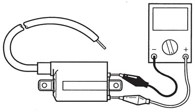
Disconnect the ignition coil connectors from the ignition coil terminals.
Connect the pocket tester (Ω x 1) to the ignition coil as shwn.
- Tester positive probe → red/black
- Tester negative probe → orange (gray)

Measure the primary coil resistance.
- Primary coil resistance: 3.57-4.83 Ω at 20°C
Connect the pocket tester (Ω x 1k) to the ignition coil as shown.
Measure the secondary coil resistance.
- Tester positive probe → spark plug lead (1)
- Tester negative probe → Orange (gray) lead (2)

- Secondary coil resistance: 10.714.5 kΩ 20°C
Is the ignition coil OK?
NO: Replace the ignition coil.
YES:
7. Pickup coil resistance
Disconnect the pickup coil coupler from the wire harness.
Connect the pocket tester (Q x 100) to the pickup coil terminal.
- Tester positive probe → gray (1)
- Tester negative probe → black/blue (2)

Measure the pickup coil resistance.
- Pickup coil resistance 189-231 Ω at 20°C (between gray and black/blue)
Is the pickup coil OK?
NO: Replace the pickup coil.
YES:
8. Main switch
Check the main switch for continuity. Refer to "Checking the switches".
Is the main switch OK?
NO: Replace the main switch.
YES:
9. Engine stop switch
Check the engine stop switch for continuity. Refer to "Checking the switches".
Is the engine stop switch OK?
NO: Replace the right handlebar switch.
YES:
10. Neutral switch
Check the neutral switch for continuity. Refer to "Checking the switches".
Is the neutral switch OK?
NO: Replace the neutral switch.
YES:
11. Sidestand switch
Check the sidestand switch for continuity. Refer to "Checking the switches".
Is the sidestand switch OK?
NO: Replace the sidestand switch.
YES:
12. Diode
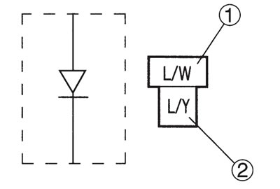
Remove the diode from the wire harness.
Check for continuity as follows:
- Tester (+) lead → Blue/White (1): Continuity
- Tester (-) lead → Blue/Yellow (2): Continuity
- Tester (+) lead → Blue/Yellow (2): No Continuity
- Tester (-) lead → Blue/White (1): No Continuity
Note: When you switch the "-" and "+" leads of the digital pocket tester the readings in the above chart will be reversed.

Is the diode OK?
NO: Replace the diode.
YES:
13. Starting circuit cut-off relay (diode)
Remove the relay unit from the wire harness.
Check for continuity as follows: Sky blue - Blue/Yellow (2)
- Tester (+) lead → SKy blue (1): Continuity
- Tester (-) lead → Blue/Yellow (2): Continuity
- Tester (+) lead → Blue/Yellow (2): No Continuity
- Tester (-) lead → Sky blue (1): No Continuity
Note: When you switch the "-" and "+" leads of the digital pocket tester the readings in the above chart will be reversed.

Is the starting circuit cut-off relay (diode) OK?
NO: Replace the starting circuit cut-off relay.
YES:
14. Wiring
Check the entire ignition system's wiring. Refer to "Circuit diagram".
Is the ignition system's wiring properly connected and without defects?
NO: Properly connect or repair the ignition system's wiring.
YES: Replace the ignitor unit.
