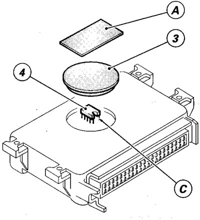
This important element can be changed as follows:
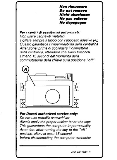
Remove the adhesive plate (A) applied during testing by the Manufacturer.

At reassembly, apply plate (B) code number 433.1.180.1A available from the Spare parts service;
Caution! This adhesive plate, applied above the rubber plug (3), guarantees that the unit parts are hermetically sealed.

Remove the rubber plug (3), located on the upper unit cover;
Remove the Eprom (4) to be changed, using the gripper 88713.1097.

When fitting the new Eprom, the reference notch (C) must be facing the pin board.
Note. To prevent damage, use tool 88713.1140 to insert the Eprom.

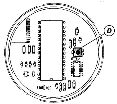
The unit also has a Trimmer (D), consisting of an adjustment screw positioned on the side of the Eprom. This screw is used to adjust the CO concentration as described in "Adjusting the throttle body". This screw has an adjustment range in which the voltage passes from 0 to 5 Volts. This is the power supply voltage of the injection system. The screw can rotate by 270P between the two limits, which have power supply values, on their terminals, of 0 Volts (min.) and 5 Volts (max.).

The centre of the range is at 2.5 Volts (13F).
Caution! Do not force beyond the limits or the Trimmer will break. Only use plastic screwdrivers.
Note. To control and/or adjust the injection times, which set the air-fuel mixture, use the "MATHESIS" tester.
