| PART NUMBER | TOOL NAME |
| HD-41609 | AMP MULTI-LOCK CRIMPER |
| SNAP-ON TT600-3 | SNAP-ON PICK |
Tyco 070 Multilock Unsealed connectors are found between wire harnesses and component wiring and may be either floating or anchored to the frame with attachment clips.
See Figure A-58. Attachment clips (1) on the pin housings are fitted to T-studs on the motorcycle frame. The T-studs identify OE connector locations. To maintain serviceability, always return connectors to OE locations after service.
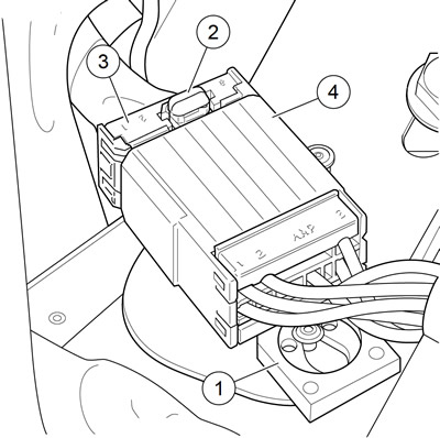
Figure A-58. Tyco 070 multilock unsealed connector: 1. Attachment clip; 2. Release button; 3. Socket housing; 4. Pin housing
Obtain the necessary tools to repair the connector and terminals.
Note. For terminal crimping use the AMP MULTI-LOCK CRIMPER (Part No. HD-41609).
Separating pin and socket housings
1. If necessary, slide connector attachment clip T-stud to the large end of the opening.
2. See Figure A-58. Press the release button (2) on the socket terminal side of the connector and pull the socket housing (3) out of the pin housing (4).
Mating pin and socket housings
1. Hold the housings to match wire color to wire color.
2. Insert the socket housing into the pin housing until it clicks in place.
3. If OE location is a T-stud, fit large opening end of attachment clip over T-stud and slide connector to engage T-stud to small end of opening.
Removing terminals from housing
1. See Figure A-59. Bend back the latch (1) to free one end of secondary lock (2) then repeat on the opposite end. Hinge the secondary lock outward.

Figure A-59. Tyco 070 multilock unsealed connector: socket and pin housings: 1. Latch; 2. Secondary lock open; 3. Pin housing; 4. Socket housing; 5. Pin terminal; 6. Socket terminal; 7. Tang (pin); 8. Tang (socket)
2. Look in the terminal side of the connector (opposite the secondary lock) and note the cavity next to each terminal.
3. Insert a pick or pin into the terminal cavity until it stops.
Note. If socket/pin terminal tool is not available, use a push pin/safety pin or a SNAP-ON PICK (Part No. SNAP-ON TT600-3).
4. Press the tang in the housing to release the terminal.
- a. Socket: Lift the socket tang (8) up.
- b. Pin: Press the pin tang (7) down.
Note. A click is heard if the tang is released.
5. Gently tug on wire to pull wire and terminal from cavity.
Inserting terminals into housing
Note. See Figure A-60. Cavity numbers are stamped into the secondary locks of both the socket and pin housings. Match the wire color to the cavity number found on the wiring diagram.
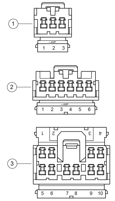
Figure A-60. Tyco 070 Multilock unsealed connector: cavity numbers on secondary locks (socket housings shown): 1. 3-place housing; 2. 6-place housing; 3. 10-place housing
1. Hold the terminal so the catch faces the tang in the chamber. Insert the terminal into its numbered cavity until it snaps in place.
Notes:
- The release button is always on the top of the connector.
- On the pin side of the connector, tangs are positioned at the bottom of each cavity, so the slot in the pin terminal (on the side opposite the crimp tails) must face downward.
- On the socket side, tangs are at the top of each cavity, so the socket terminal slot (on the same side as the crimp tails) must face upward.
2. Gently tug on wire end to verify that the terminal is locked in place.
3. Rotate the hinged secondary lock inward until tabs fully engage latches on both sides of connector.
Preparing wire leads for crimping
1. Strip wire lead removing 5/32 in (4.0 mm) of insulation.
2. See Figure A-61 and Figure A-62. Select the pin/socket terminals from the parts catalog and identify the insulation crimp tails (1) and the wire crimp tails (2) and the groove for the crimp tool locking bar (3).

Figure A-61. Tyco 070 Multilock unsealed connector: pin terminal: 1. Insulation crimp tail; 2. Wire crimp tail; 3. Locking bar groove
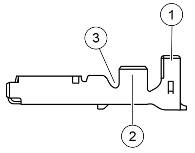
Figure A-62. Tyco 070 Multilock unsealed connector: socket terminal: 1. Insulation crimp tail; 2. Wire crimp tail; 3. Locking bar groove
3. Identify the wire lead gauge and the corresponding crimper tool and nesting die. Referto Table A-8.
Table A-8. AMP Multilock connector: crimp tool wire gauge/nest
| WIRE GAUGE | NEST |
| 20 | Front |
| 16 | Middle |
| 18 | Rear |
Crimping terminals to leads
Note. Crimping with the AMP Multi-lock Crimper is a one step operation. One squeeze crimps both the wire core and the insulation tails.
1. See Figure A-63. Squeeze the handles to cycle the AMP MULTI-LOCK CRIMPER (Part No. HD-41609) to the fully open position (1).
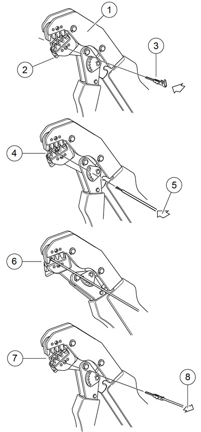
Figure A-63. Tyco 070 Multilock unsealed connector: terminal crimping procedure: 1. Open position; 2. Locking bar flange; 3. Insert contact; 4. Release locking bar; 5. Insert lead; 6. Squeeze; 7. Raise locking bar; 8. Remove crimped terminal
2. Raise locking bar by pushing up on bottom flange (2).
Note. See Figure A-61 and Figure A-62. Hold the terminal with the insulation crimp tail (1) facing up. The tool will hold the terminal by the locking bar groove (3) and simultaneously crimp around the stripped lead and the insulation.
3. See Figure A-63. With the insulation crimp tail facing upward, insert terminal (pin or socket) (3) through the locking bar, so that the closed side of the terminal rests on the nest of the crimp tool.
4. Release locking bar to lock position of contact (4). When correctly positioned, the locking bar fits snugly in the space at the front of the core crimp tails.
5. Insert stripped end of lead (5) until ends make contact with locking bar.
6. Position wire that the wide pair of crimp tails squeeze bare wire strands, while the narrow pair folds overthe insulation material.
7. Squeeze handle of crimp tool until tightly closed. Tool automatically opens when the crimping sequence is complete.
8. Raise up locking bar (7) to remove crimped terminal.
Inspecting crimped terminals
See Figure A-64. Inspect the wire core crimp (2) and insulation crimp (1). Distortion should be minimal.
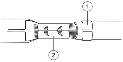
Figure A-64. Tydo 070 Multilock unsealed connector: terminal crimp: 1. Insulation crimp; 2. Wire core crimp
