| PART NUMBER | TOOL NAME |
| HD-41475 | DEUTSCH TERMINAL REPAIR KIT |
| HD-41475-100 | FLAT BLADE L-HOOK |
Deutsch DT sealed connectors are colored coded for location purposes. DT connectors associated with left side accessories, such as the front and rear left turn signals, are gray. All other DT connectors are black.
Notes:
- A DEUTSCH TERMINAL REPAIR KIT (Part No. HD-41475) contains a selection of seals and seal plugs, locking wedges, attachment clips and terminals.
- Also included is a FLAT BLADE L-HOOK (Part No. HD-41475100) used to remove locking wedges, compartmented storage box and carrying case.
Separating pin and socket housings
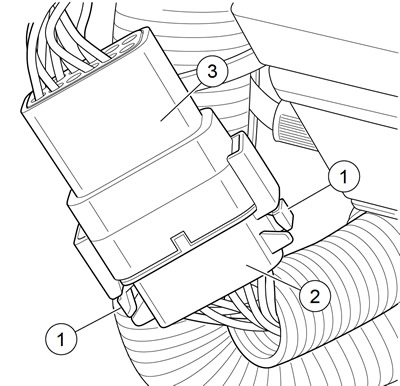
See Figure A-29. To separate the connector halves, Press the external latch(es) (1) on the socket housing (2) while rocking the pin (3) and socket housings.

Figure A-29. Deutsch DT sealed connector: 1. External latch; 2. Socket housing; 3. Pin housing
Notes:
- Generally the socket housing is found on the accessory side, while the pin housing is attached to the wiring harness.
- Six-place and smaller Deutsch connectors have one latch on the connector.
- Eight- and twelve-place connectors have a latch on each side. Simultaneously press both latches to separate the connector.
Mating pin and socket housings
1. Align the connectors to match the wire lead colors.
- a. For One External Latch: Six-place and smaller Deutsch connectors have one external latch on the socket housing. To join the housings, align the latch on the socket side with the latch cover on the pin side.
- b. For Two External Latches: Align the tabs on the socket housing with the grooves on the pin housing.
2. Insert socket housing into pin housing until it snaps or clicks into place.
Note. For Two External Latches: If latches do not click (latch), press on one side of the connector until that latch engages then press on the opposite side to engage the other latch.
3. If necessary, fit the attachment clip to the pin housing.
4. Place large end of slot on attachment clip over T-stud on frame. Push assembly forward to engage small end of slot.
Removing socket terminals
1. See Figure A-30. Insert a small screwdriver between the socket housing and locking wedge in-line with the groove (in-line with the pin holes if the groove is absent). Turn the screwdriver 90 degrees to pop the wedge up and remove the secondary locking wedge.

Figure A-30. Deutsch DT sealed connector: remove secondary locking wedge
2. See Figure A-33. Use a pick or small screwdriver to press terminal latches inside socket housing and back out sockets through holes in rear wire seal.

Figure A-33. Deutsch DT sealed connector: press terminal latch and back out pin
Note. If wire leads require new terminals, see the instructions for crimping terminals.
Installing socket terminals
1. Match wire lead color to connector cavity.
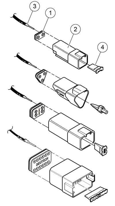
2. See Figure A-32. Fit rear wire seal (1) into back of socket housing (2), if removed.

Figure A-32. Deutsch DT sealed connector: 2, 3, 4 and 12-place socket housings: 1. Wire seal; 2. Socket housing; 3. Wire lead; 4. Internal seal; 5. Secondary locking wedge; 6. Seal plug
3. Grasp wire lead (3) approximately 1.0 in (25.4 mm) behind the socket terminal. Gently push socket through hole in wire seal into its chambers until it clicks in place.
4. A tug on the wire will confirm that it is properly locked in place.
Note. Install seal plugs (6) into unused chambers. If removed, seal plugs must be replaced to seal the connector.
5. Install internal seal (4) on lip of socket housing, if removed.
6. Insert tapered end of secondary locking wedge (5) into socket housing and press down until it snaps in place. The wedge fits into the center groove within the socket housing and holds the terminal latches tightly closed.
Notes:
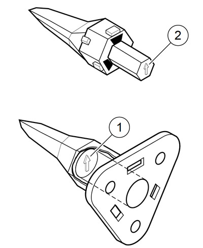
- See Figure A-31. While rectangular wedges do not require a special orientation, align arrow (1) on conical secondary locking wedge towards external latch for three-place connectors.
- If the secondary locking wedge does not slide into position easily, check the installation of all the terminals. Unseated terminals prevent the locking wedge from proper installation.

Figure A-31. Deutsch DT sealed connector: 3-place locking wedges: 1. Arrow on socket locking wedge; 2. Arrow on pin locking wedge
Removing pin terminals
1. Use the hooked end of a stiff piece of mechanics wire, a needle nose pliers or the FLAT BLADE L-HOOK (Part No. HD-41475-100) to remove the secondary locking wedge.
2. Gently press terminal latches inside pin housing and back out pins through holes in wire seal.
Notes:
- If wire leads require new terminals, see the instructions for crimping terminals.
- The 8-place and 12-place gray and black connectors are not interchangeable. If replacing both the socket and pin housings, the black may be substituted for the gray.
- The socket and pin housings of all other connectors are interchangeable. Black may be mated with the gray since the alignment tabs are absent and the orientation of the external latch is the same.
Installing pin terminals
1. See Figure A-34. Fit wire seal (1) into back of pin housing (2).

Figure A-34. Deutsch DT sealed connector: 2, 3, 4 and 12-place pin housings: 1. Wire seal; 2. Pin housing; 3. Pin terminal; 4. Locking wedge
2. Grasp wire lead approximately 1.0 in (25.4 mm) behind the pin terminal (3). Gently push pin through holes in wire seal into its respective numbered chamber until it "clicks" in place.
Note. A tug on the wire lead will confirm that a pin is locked in place.
3. Insert tapered end of secondary locking wedge (4) into pin housing. Press down until it snaps in place.
Notes:
- The wedge fits in the center groove of the pin housing and holds the terminal latches tightly closed.
- See Figure A-31. While rectangular wedges do not require a special orientation, align arrow (1) on conical secondary locking wedge towards external latch for three-place connectors.
- If the secondary locking wedge does not slide into position easily check the installation of all the terminals. Unseated terminals prevent the locking wedge from proper installation.
Crimping terminals
Identify which of the types of Deutsch terminals are used with the connector. Follow the corresponding crimping instructions. Refer to Table A-2.
Table A-2. Deutsch connector: terminal crimping instructions
| TYPE | CRIMPING INSTRUCTIONS |
| DT Sealed (with crimp tails) | A.14 DEUTSCH DT SEALED TERMINAL REPAIR |
| DTM Mini Sealed Terminal (solid barrel) | A.16 DEUTSCH DTM SEALED SOLID BARREL MINI TERMINAL REPAIR |
| DTM Mini Sealed Terminal (with crimp tails) | A.15 DEUTSCH DTM SEALED MINI TERMINAL REPAIR |
