Warning! Stop the engine when refueling or servicing the fuel system. Do not smoke or allow open flame or sparks near gasoline. Gasoline is extremely flammable and highly explosive, which could result in death or serious injury.
Warning! Do not replace the special Teflon coated fuel pump wiring with ordinary bulk wire. Ordinary insulation materials can deteriorate when put in contact with gasoline and cause an explosion, which could result in death or serious injury.
Warning! Do not use solvents or other products that contain chlorine on plastic fuel system components. Chlorine can degrade plastic fuel system components, which can cause a loss of fuel system pressure or engine stalling and could result in death or serious injury.
Carefully inspect fuel hose for cuts, tears, holes or other damage. Replace hose if any damage is found. Even a small hole can cause a reduction in fuel pressure.
Removal
Warning! To prevent spray of fuel, purge system of high-pressure fuel before supply line is disconnected. Gasoline is extremely flammable and highly explosive, which could result in death or serious injury.
1. Purge the fuel supply hose of high pressure gasoline. Disconnect fuel supply hose from fuel pump module. See 4.4 FUEL TANK: XL MODELS or 4.5 FUEL TANK: XR 1200X.
Warning! To prevent accidental vehicle start-up, which could cause death or serious injury, remove main fuse before proceeding.
2. Remove main fuse.
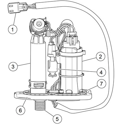
3. See Figure 4-74. Unplug fuel pump harness connector [141] (1), located forward of fuse/relay block on left side of vehicle.

Figure 4-74. Fuel pump module: 1. Fuel pump harness connector [141]; 2. Fuel pump; 3. Fuel filter housing; 4. Sending unit float; 5. Quick-connect fitting; 6. Cover plate; 7. Cover plate seal
4. Drain and remove fuel tank from vehicle. See 4.4 FUEL TANK: XL MODELS or 4.5 FUEL TANK: XR 1200X.
5. See Figure 4-75. Lay fuel tank upside-down on a soft cloth.

Figure 4-75. Fuel pump module: all models: 1. Fuel tank; 2. Fuel pump module; 3. Screw (5); 4. Fuel pump harness; 5. Quick-connect fitting
6. Remove five screws (3).
7. Carefully lift fuel pump module out of fuel tank. See Figure 4-76. To facilitate removal, tilt module when it is almost completely free of fuel tank.

Figure 4-76. Removing/installing fuel pump module: all models
8. See Figure 4-74. Remove and discard cover plate seal (7).
Disassembly
The disassembly procedure consists of the following groups:
- Pressure regulator and filter housing.
- Fuel pump assembly and pump bracket.
- Low fuel level sensor assembly.
- Fuel pump.
Note. See Figure 4-77. Maintain the relative positions of the wiring harness cable straps (1) and pump assembly clamp (2).

Figure 4-77. Fuel pump cable straps and pump clamp: 1. Cable strap (3); 2. Pump assembly clamp; 3. Pump bracket; 4. Filter housing hose
Pressure regulator and filter housing
1. See Figure 4-77. Remove cable strap (1) securing wiring harness to the filter housing hose (4).
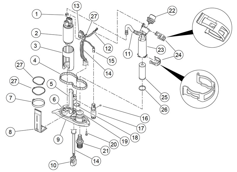
2. See Figure 4-78. Remove ground clip (2) from top of filter housing (23).

Figure 4-78. Fuel pump and sender assembly: 1. Clamp; 2. Fuel pump; 3. Pump insulator; 4. Cover plate seal; 5. Pump bracket; 6. Screw w/lockwasher (3); 7. Pump assembly clamp; 8. Inlet sock; 9. Cover plate; 10. Fuel pump/sender harness connector [141]; 11. Filter housing hose; 12. Ground clip; 13. Fuel pump harness connector [86]; 14. Fuel pump/sender harness; 15. Low fuel level sensor connector; 16. Push nut; 17. Low fuel level sensor; 18. Retaining ring; 19. Filter housing mount; 20. Screw (5); 21. Fuel outlet quick-connect fitting; 22. Pressure regulator; 23. Filter housing; 24. Retaining clip (2); 25. Fuel filter element; 26. O-ring; 27. Cable strap
3. Remove and discard clamp (1). Remove filter housing hose from top of fuel pump (2).
4. Remove retaining clip (24) from top of filter housing and remove pressure regulator (22).
5. Remove second retaining clip (24) from bottom of filter housing and remove filter housing. Remove fuel filter element (25) from housing.
6. Remove O-ring (26) from filter housing mount (19).
Fuel pump assembly and pump bracket
1. See Figure 4-77. Make note of the location of any cable straps securing wiring harness to the fuel pump bracket (3). Remove cable straps.
2. See Figure 4-78. Unplug fuel pump harness connector [86] (13).
3. Unplug low fuel level sensor connector from fuel pump/sender harness (14).
4. Remove and discard clamp (1). Remove filter housing hose (11) from top of fuel pump (2).
5. Remove and discard pump assembly clamp (7). Remove pump assembly with pump insulator (3) from pump bracket (5).
6. Remove push nut (16) and low fuel level sensor assembly (17) from pump bracket.
7. Remove three screws w/lockwashers (6) and remove pump bracket from cover plate (9).
Low fuel level sensor assembly
1. See Figure 4-77. Make note of the location of cable strap (1) securing low fuel level sensor connector to filter housing hose (4). Remove cable strap.
2. See Figure 4-78. Unplug the fuel pump/sender harness connector (15) from the low fuel level sensor (17).
3. Remove push nut (16) and low fuel level sensor assembly (17) from pump bracket (5).
Assembly
| FASTENER | TORQUE VALUE | |
| Fuel pump bracket mounting screw | 19-36 in·lbs | 2.1-4.1 Nm |
The assembly procedure consists of the following groups:
- Low fuel level sensor assembly.
- Fuel pump assembly and pump bracket.
- Pressure regulator and filter housing.
Low fuel level sensor assembly
Note. The low fuel lamp will not turn off until there is sufficient fuel in the tank, the ignition switch has been turned off and on and the motorcycle has begun forward speed.
1. See Figure 4-78. Install low fuel level sensor assembly (17) onto pump bracket (5). Secure with push nut (16).
2. Plug the fuel pump/sender harness connector (15) into the low fuel level sensor (17).
3. See Figure 4-77. Secure low fuel level sensor connector and fuel pump/sender harness to filter housing hose (4) with cable strap (1).
Fuel pump assembly and pump bracket
1. See Figure 4-78. Install pump bracket (5) onto cover plate (9). Secure with three screws w/lockwashers (6). Tighten to 19-36 in·lbs (2.1-4.1 Nm).
2. Install low fuel level sensor assembly (17) onto pump bracket. Secure with push nut (16).
3. Install fuel pump assembly (2) with pump insulator (3) onto pump bracket. Secure with pump assembly clamp (7) (for relative position of clamp, see Figure 4-77.)
4. Install filter housing hose (11) on top of fuel pump. Secure with clamp (1).
5. Plug in fuel pump harness connector [86] (13).
6. See Figure 4-77. Secure fuel pump/sender harness to fuel pump bracket (3) with cable straps (1).
Pressure regulator and filter housing
1. See Figure 4-78. Install the new O-ring onto filter housing mount (19).
2. Install fuel filter element (25) into filter housing (23). Install filter housing onto filter housing mount. Secure with retaining clip (24) at bottom of housing, making sure that clip is oriented exactly as shown in Figure 4-78.
3. Install pressure regulator (22) on top of filter housing. Secure with second retaining clip (24), making sure that clip is oriented exactly as shown in Figure 4-78.
4. Install filter housing hose (11) on top of fuel pump (2). Secure with clamp (1).
5. Install ground clip (12) on top of filter housing.
6. See Figure 4-77. Secure fuel pump/sender harness to filter housing hose (4) with cable strap (1).
Installation
| FASTENER | TORQUE VALUE | |
| Fuel pump module mounting screw | 40-45 in·lbs | 4.5-5.1 Nm |
1. See Figure 4-78. Install new cover plate seal (4) into groove in cover plate (9).
2. See Figure 4-76. Carefully install fuel pump module into fuel tank.
- a. Tilt module.
- b. Lower it into fuel tank.
- c. Straighten module to complete installation.
3. See Figure 4-79. Install screws. Tighten to 40-45 in·lbs (4.5-5.1 Nm) in sequence.

Figure 4-79. Fuel pump module torque sequence
4. Install fuel tank. See 4.4 FUEL TANK: XL MODELS or 4.5 FUEL TANK: XR 1200X.
- a. Verify that the fuel pump harness fits in wire harness caddy latch clip with loop in harness between latch clip and fuel pump module.
- b. Plug in fuel pump harness connector [141].
- c. Connect vent hose to fuel tank vent nipple.
5. Connect fuel hose to fuel tank. Fill fuel tank. Check for leaks around fuel pump module. See 4.4 FUEL TANK: XL MODELS or 4.5 FUEL TANK: XR 1200X.
6. Install main fuse.
7. Close left side cover.
8. Check for leaks:
- a. Turn ignition switch to ON.
- b. Verify fuel pump is activated.
- c. Check for leaks at quick connect.
- d. Turn ignition switch to OFF.
