Purging and disconnecting fuel supply hose
When servicing the fuel system, do not smoke or allow open flame or sparks in the vicinity. Gasoline is extremely flammable and highly explosive, which could result in death or serious injury.
To prevent spray of fuel, purge system of high-pressure fuel before supply line is disconnected. Gasoline is extremely flammable and highly explosive, which could result in death or serious injury.
1. Purge the fuel supply line of high pressure gasoline.
- a. Remove left side cover. See 2.18 LEFT SIDE COVER.
- b. See Figure 4-6. Remove fuel pump connector from ECM caddy cover (2).
- c. Unplug fuel pump connector [141].
- d. Start engine and allow vehicle to run.
- e. When engine stalls, operate starter for 3 seconds to remove any remaining fuel from fuel hose.
- f. Shut off ignition.
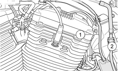
Figure 4-6. Fuel pump connector: XL Models: 1. Fuel pump wiring; 2. ECM caddy cover (fuel pump connector inside)
2. See Figure 4-7. Push up on release sleeve (1) on fuel pump quick-connect fitting and pull down on fuel supply hose fitting (2) to disconnect fuel supply hose (3) from fuel pump module (4). Immediately clean up any fuel spills.
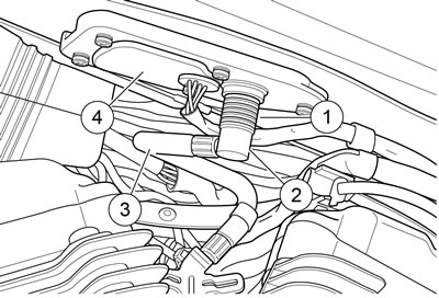
Figure 4-7. Fuel tank quick-connect fitting: 1. Release sleeve (quick-connect fitting); 2. Fuel supply hose fitting; 3. Fuel supply hose; 4. Fuel pump module
Removing fuel tank
To prevent accidental vehicle start-up, which could cause death or serious injury, remove main fuse before proceeding.
1. Remove main fuse.
2. Remove seat.
Notes:
- If the fuel tank is being removed only to gain access to items otherwise hidden, it is not necessary to drain the fuel from the tank. If the fuel tank is to be disassembled or repaired, follow the step below to drain the fuel.
- Drain fuel into an approved container.
3. Drain fuel tank:
- a. Obtain a suitable fuel transfer pump with a long, flexible nozzle.
- b. Position vehicle upright. Remove fuel tank filler cap.
- c. Insert fuel transfer pump nozzle into fuel tank filler spout. Aim nozzle toward right side of fuel tank to avoid contacting and damaging fuel pump assembly.
- d. Direct the pump output into an approved container.
- e. Pump fuel until fuel tank is empty.
- f. Immediately wipe up any spilled fuel.
4. See Figure 4-8. Remove vent hose (1) from fuel tank vent nipple. Remove cable clip (3) securing fuel pump wiring harness (2) to mounting boss on H-bracket.
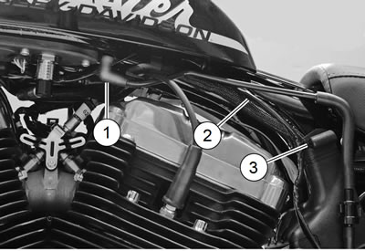
Figure 4-8. Fuel tank vent hose: 1. Vent hose; 2. Fuel pump wiring harness; 3. Cable clip
5. Unplug fuel pump connector [141].
6. Remove protective caps, locknuts, screws and washers from front and rear of fuel tank.
7. Place a clean, soft cloth over front of fuel tank to keep tank from contacting top fork clamp and damaging paint. Lift up rear of fuel tank. Remove fuel pump harness from clip on wire harness caddy latch clip on frame backbone.
8. Lift fuel tank off motorcycle.
9. Remove fuel pump assembly. See 4.16 FUEL PUMP.
Cleaning and inspection
Warning! When servicing the fuel system, do not smoke or allow open flame or sparks in the vicinity. Gasoline is extremely flammable and highly explosive, which could result in death or serious injury.
1. Clean fuel tank interior with commercial cleaning solvent or a soap and water solution. Shake fuel tank to agitate cleaning agent.
2. Thoroughly flush fuel tank after cleaning. Allow fuel tank to air dry.
3. Carefully inspect fuel hose and vent hose for damage, cuts, cracks, holes, wear or general deterioration. Replace as necessary.
4. Inspect the fuel tank for leaks or other damage. If a damaged fuel tank cannot be successfully repaired, replace it.
Installing fuel tank
| FASTENER | TORQUE VALUE | |
| Fuel tank fasteners: XL Models | 15-20 ft·lbs | 20.3-27.1 Nm |
Note. Verify wiring harnesses are not pinched between fuel tank and frame during tank installation.
1. Install fuel pump into fuel tank using new gasket. See 4.16 FUEL PUMP.
2. See Figure 4-9. Position fuel tank on motorcycle. Verify that front fuel tank brackets are located outboard of ignition coil bracket (8).
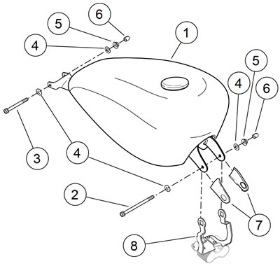
Figure 4-9. Fuel tank mounting (typical): 1. Fuel tank (typical); 2. Screw (long); 3. Screw (short); 4. Washer (4); 5. Locknut (2); 6. Protective cap (2); 7. Cosmetic cover (2); 8. Ignition coil bracket
3. Install front fastener.
- a. Place washer (4) on long screw (2).
- b. From right to left, push screw through front fuel tank bracket, ignition coil bracket and frame.
- c. Place second washer over screw.
- d. Hand-start locknut (5).
4. See Figure 4-10. Place a clean, soft cloth over front of fuel tank to keep tank from contacting top fork clamp and damaging paint.
5. Lift up rear of fuel tank.
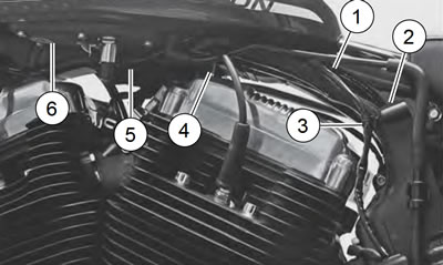
Figure 4-10. Fuel pump wiring harness routing: 1. Fuel pump wiring harness; 2. Cable clip mounting boss on ECM caddy; 3. Cable clip; 4. Wire harness caddy latch clip; 5. Fuel pump wiring harness loop; 6. Fuel pump module
6. Place fuel pump wiring harness (1) into clip on wire harness caddy latch clip on frame backbone tube. Verify that the harness forms a loop (5) between caddy latch clip and fuel pump module (6). Do not pinch harness between fuel tank and frame backbone tube.
7. Route fuel pump wiring harness down along left side of H-bracket. Secure with cable clip (3). Push clip into hole in mounting boss (2) on H-bracket.
8. Install fuel tank.
- a. Lower rear of fuel tank into position.
- b. See Figure 4-9. Place washer (4) on short screw (3).
- c. From right to left, push screw through rear fuel tank bracket and frame.
- d. Place second washer over screw
- e. Hand-start locknut (5).
- f. Tighten both front and rear fuel tank mounting fasteners to 15-20 ft·lbs (20.3-27.1 Nm).
- g. Install protective caps (6) on screw ends.
9. See Figure 4-8. Install vent hose onto fuel tank vent nipple.
10. Connect the fuel pump connector [141] housings.
Connecting fuel hose and filling fuel tank
Warning! To prevent spray of fuel, be sure quick-connect fittings are properly mated. Gasoline is extremely flammable and highly explosive, which could result in death or serious injury.
1. See Figure 4-7. Connect fuel hose.
- a. Push up on release sleeve (1).
- b. Push fuel hose fitting (2) into fuel pump module fuel pump quick-connect fitting.
- c. Pull down on release sleeve to lock quick-connect fitting.
- d. Tug on fuel hose fitting to make sure it is securely locked in place.
2. See Figure 4-8. Install vent hose onto vent nipple on fuel tank.
Warning! Use care when refueling. Pressurized air in fuel tank can force gasoline to escape through filler tube. Gasoline is extremely flammable and highly explosive, which could result in death or serious injury.
Warning! Avoid spills. Slowly remove filler cap. Do not fill above bottom of filler neck insert, leaving air space for fuel expansion. Secure filler cap after refueling. Gasoline is extremely flammable and highly explosive, which could result in death or serious injury.
3. Fill fuel tank and carefully inspect for leaks around fuel pump module.
4. Install main fuse.
5. Turn ignition switch ON and verify fuel pump is activated. Carefully inspect for leaks at quick-connect fitting. Turn ignition switch OFF.
Warning! After installing seat, pull upward on seat to be sure it is locked in position. While riding, a loose seat can shift causing loss of control, which could result in death or serious injury.
6. Install seat.
Vapor valve
Warning! Excessive pressure can build in the fuel tank if vapor valve is not mounted vertically with long fitting to top. Leaks due to excessive pressure can cause a fire or explosion, which could result in death or serious injury.
See Figure 4-11. The fuel tank is vented through a standpipe (vent tube) within the tank. A hose (1) at the base of the fuel tank is connected to the standpipe.

Figure 4-11. Vapor valve: 1. Fuel-to-vapor valve hose; 2. Vapor valve; 3. Vapor valve clip; 4. Vapor valve-to-atmosphere hose (non-evapor-ative emission controlled models)
Warning! Keep vent and vapor valve lines away from exhaust and engine. Gasoline is extremely flammable and highly explosive, which could result in death or serious injury.
The fuel tank vent hose is connected to a vapor valve (2). This valve attaches into a clip (3) on the ECM caddy behind the left side cover. On non-evaporative emission controlled models, another hose (4) vents the vapor valve to the atmosphere. On evaporative emission controlled models, that hose is routed to the charcoal canister. See 4.20 EVAPORATIVE EMISSIONS CONTROL.
Notes:
- Mount the vapor valve in an upright position with the longer fitting positioned at the top or excessive fuel vapor pressure may build up within the fuel tank.
- Do NOT force vapor valve into clip. Forcing valve in to clip could cause clip to break, necessitating replacement of the ECM caddy.
