
Removal
Warning! Stop the engine when refueling or servicing the fuel system. Do not smoke or allow open flame or sparks near gasoline. Gasoline is extremely flammable and highly explosive, which could result in death or serious injury.
1. Purge the fuel supply hose of high pressure gasoline. Disconnect fuel supply hose from fuel pump module. See 4.5 FUEL TANK: XR 1200X.
Warning! To prevent accidental vehicle start-up, which could cause death or serious injury, remove main fuse before proceeding.
2. Remove main fuse.
3. Remove fuel tank and air box. See 4.5 FUEL TANK: XR 1200X and 4.3 AIR CLEANER ASSEMBLY, XR 1200X.
4. See Figure 4-43. Remove screws (3), fastener (1) and fastener (2).
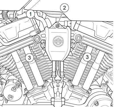
Figure 4-43. Induction module cover: XR 1200X: 1. Fastener, wire form; 2. Fastener, to induction module; 3. Screws (2)
5. Pull cover away from induction module and disengage cable retainer from back side of cover. Remove cover.
6. Disengage throttle cables from induction module. See 2.28 THROTTLE CABLES: ALL MODELS.
7. See Figure 4-44. Unplug the following connectors:
- a. Front fuel injector (3) [84],
- b. Rear fuel injector (4) [85],
- c. TMAP sensor (5) [80],
- d. IAC (6) [87],
- e. TPS (7) [88].
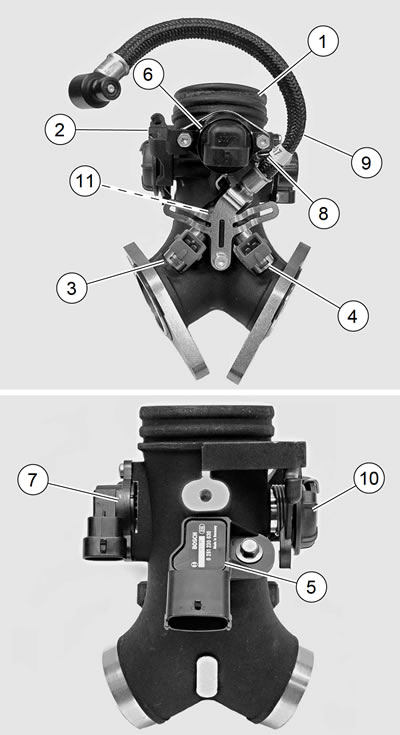
Figure 4-44. Induction module: 1. Induction module; 2. Throttle cable bracket; 3. Front fuel injector [84A]; 4. Rear fuel injector [85A]; 5. TMAP sensor [80A]; 6. IAC [87A]; 7. TPS [88A]; 8. Purge hose fitting (EVAP models only); 9. Fuel supply hose; 10. Throttle wheel; 11. Fuel rail (not visible)
8. EVAP Controlled Models: Remove purge hose from fitting (8).
9. See Figure 4-45. Disconnect oil line flare nuts (1) from flare fittings (2) in cylinder heads. Remove flare fittings (2) from cylinder heads.
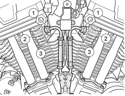
Figure 4-45. Remove induction module: 1. Flare nuts; 2. Flare fittings; 3. Fastener
10. Loosen but do not remove left side screws holding induction module to cylinder head.
11. Remove two screws (3) securing induction module to cylinder heads on right side of vehicle.
12. Remove induction module from engine.
Disassembly
| PART NUMBER | TOOL NAME |
| HD-25070 | HEAT GUN |
1. See Figure 4-46. Remove retainer (7). Remove fuel rail (8) with hose (4) and injectors (10) from the induction module.

Figure 4-46. Induction module: 1. TPS; 2. O-ring; 3. IAC; 4. Fuel hose; 5. Nylon washer (included with hose (4)); 6. O-ring (included with hose (4)); 7. Retainer; 8. Fuel rail; 9. O-ring (4) (included in hardware and O-ring kit); 10. Fuel injector (2); 11. Screw; 12. Throttle cable bracket; 13. Intake seal; 14. Mounting flange; 15. TMAP sensor; 16. Screw, IAC (2)
2. Remove hose (4) and injectors (10) from fuel rail.
3. Remove cable bracket (12).
Note. Screws (16) MUST be heated to soften the thread sealant and avoid breakage during removal. Use ONLY HEAT GUN (Part No. HD-25070) to heat the screws. NEVER use an open flame.
4. Remove IAC (3). See 4.10 IDLE AIR CONTROL (IAC), Removal: XR 1200X.
5. Remove TMAP (15), and TPS (1).
6. Remove mounting flanges (14) and seals (13).
Assembly
| FASTENER | TORQUE VALUE | |
| IAC mounting screw: XR 1200X | 60 in·lbs | 6.8 Nm |
| Throttle cable bracket screw: XR 1200X | 60 in·lbs | 6.8 Nm |
1. See Figure 4-46. Install the following:
- a. TPS. See 4.6 THROTTLE POSITION SENSOR (TPS).
- b. TMAP sensor. See 4.11 TEMPERATURE MANIFOLD ABSOLUTE PRESSURE (TMAP) SENSOR.
- c. IAC. See 4.10 IDLE AIR CONTROL (IAC).
Note. Do not install IAC mounting screw on throttle wheel side of induction module until cable bracket is installed. Install other IAC mounting screw but do not tighten at this time.
2. Install cable bracket (12) onto induction module:
- a. Apply LOCTITE 243 MEDIUM STRENGTH THREADLOCKER AND SEALANT (blue) to the threads of screw (11).
- b. Install screw finger-tight.
- c. Tighten both IAC mounting screws to 60 in·lbs (6.8 Nm).
- d. Tighten screw (11) to 60 in·lbs (6.8 Nm).
3. Install fuel injectors, fuel rail and fuel hose. See 4.15 FUEL INJECTORS.
Installation
| FASTENER | TORQUE VALUE | |
| Intake manifold mounting screw: XR 1200X | 90-120 in·lbs | 10.3-13.6 Nm |
| Cylinder head oil feed flare fitting: XR 1200X | 22-26 ft·lbs | 29.8-35.3 Nm |
| Cylinder head oil feed line flare nut: XR 1200X | 13-17 ft·lbs | 17.6-23.0 Nm |
| Induction module coverto cylinder head sockethead bolts: XR 1200X | 20-24 ft·lbs | 27.1-32.5 Nm |
| Induction module coverto induction module fastener: XR 1200X | 90-120 in·lbs | 10.2-13.6 Nm |
| Induction module coverto wire form fastener: XR 1200X | 90-120 in·lbs | 10.2-13.6 Nm |
1. Install the two left side mounting screws two or three turns into the heads.
2. See Figure 4-47. Install mounting flanges (3) on induction module with counterbore (1) facing toward the engine.
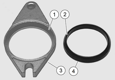
Figure 4-47. Mounting flange and seal: 1. Beveled counterbore; 2. Beveled edge; 3. Mounting flange; 4. Tapered seal
3. Install new seals (4).
- a. Placed the beveled edge facing the mounting flange counterbore.
- b. Rotate the flange to the slotted mounting hole is on the same side as the IAC solenoid.
Notes:
- Verify that the flanges are installed on the manifold.
- Verify that the rubber seals are in place.
4. See Figure 4-45. Place induction module assembly in position between engine heads. Slide open slotted ends of mounting flanges under heads of two mounting screws on left side of engine.
5. While holding induction module assembly in place, install two mounting screws (3) into remaining mounting flange holes. Tighten all four screws finger-tight.
6. Tighten to 90-120 in·lbs (10.3-13.6 Nm).
7. Inspect O-rings on flare fittings (2). Replace as necessary.
8. Install flare fittings in cylinder heads. Tighten to 22-26 ft·lbs (29.8-35.3 Nm).
9. Connect oil line flare nuts (1) to flare fittings (2). Tighten to 13-17 ft·lbs (17.6-23.0 Nm).
10. Install throttle cables. See 2.28 THROTTLE CABLES: ALL MODELS.
11. Adjust throttle and idle cables. See 1.13 THROTTLE CONTROL.
12. EVAP Controlled Models: See Figure 4-44. Install purge hose onto fitting (8) on induction module (1).
Note. XR 1200X: See Figure 4-48. The fuel injector harness leads must NEVER be routed between the retaining bracket (3) and the induction module body (4). Improper routing will result in chafing of the insulation resulting in poor engine performance.
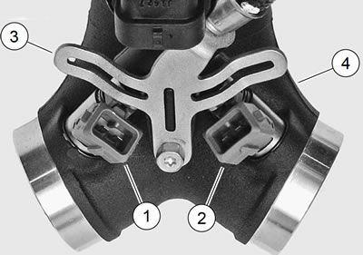
Figure 4-48. Fuel injectors and retaining bracket: 1. Front fuel injector [84]; 2. Rear fuel injector [85]; 3. Retaining bracket; 4. Induction module
13. See Figure 4-44. Plug in the following connectors: a. Front fuel injector (3) [84],
- b. Rear fuel injector (4) [85],
- c. TMAP sensor (5) [80],
- d. IAC (6) [87],
- e. TPS (7) [88].
14. Secure TPS harness to cover with a new cable strap with anchor.
15. Install induction module cover. Finger tighten the fasteners.
16. Tighten:
- a. Socket headbolts to 20-24 ft·lbs (27.1-32.5 Nm).
- b. Cover-to-induction module fastener to 90-120 in·lbs (10.2-13.6 Nm).
- c. Cover-to-wire form fastener to 90-120 in·lbs (10.213.6 Nm).
17. Install air box. See 4.3 AIR CLEANER ASSEMBLY, XR 1200X.
18. Install fuel tank. See 4.4 FUEL TANK: XL MODELS.
19. Fill fuel tank. Check for leaks around fuel pump module and quick connector. See 4.4 FUEL TANK: XL MODELS.
20. Install main fuse.
21. Close left side cover.
22. Reset IAC to park.
- a. Turn ignition to ON.
- b. Turn ignition to OFF.
23. Start engine. Check for fuel leaks.