Warning! Stop the engine when refueling or servicing the fuel system. Do not smoke or allow open flame or sparks near gasoline. Gasoline is extremely flammable and highly explosive, which could result in death or serious injury.
See Figure 4-56 or Figure 4-57. The Temperature Manifold Absolute Pressure (TMAP) sensor performs the dual functions of monitoring air temperature and air pressure in the intake manifold. See the electrical diagnostic manual.

Figure 4-56. TMAP location: XL models | 
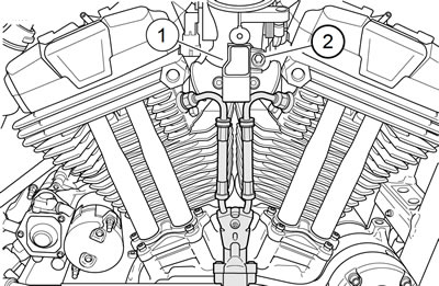
Figure 4-57. TMAP location: XR 1200X |
Removal: XL models
Warning! To prevent spray of fuel, purge system of high-pressure fuel before supply line is disconnected. Gasoline is extremely flammable and highly explosive, which could result in death or serious injury.
Warning! Gasoline can drain from quick-connect fitting when removing fuel line. Gasoline is extremely flammable and highly explosive, which could result in death or serious injury. Wipe up spilled fuel immediately and dispose of rags in a suitable manner.
1. Remove main fuse.
2. Remove air cleaner assembly. See 4.3 AIR CLEANER ASSEMBLY.
3. Remove fuel rail and fuel injectors. See 4.15 FUEL INJECTORS. This will allow access to the two screws that secure the induction module to the intake manifold.
4. See Figure 4-56. Remove two screws (2) and separate induction module from intake manifold. See 4.8 INDUCTION MODULE: XL MODELS.
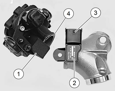
5. See Figure 4-58. Pull induction module away from intake manifold far enough so that TMAP sensor retaining bracket (1) clears TMAP sensor body (2).

Figure 4-58. TMAP sensor removal/installation: 1. TMAP sensor retaining bracket; 2. TMAP sensor; 3. Sensor connector [80A]; 4. O-ring
6. Unplug harness connector [80B] from TMAP connector [80A] (3).
7. Grasp TMAP sensor and with a gentle twisting motion, pull sensor straight up out of intake manifold body.
Installation: XL models
| FASTENER | TORQUE VALUE | |
| Induction module screw: XL Models | 35 in·lbs | 4.0 Nm |
1. See Figure 4-59. If re-using TMAP sensor (1), inspect Oring (2) in groove of sensor for cuts, tears or signs of deterioration. Replace if necessary.

Figure 4-59. TMAP sensor: 1. TMAP sensor; 2. O-ring
2. Apply a thin coat of clean engine oil to TMAP sensor Oring.
3. See Figure 4-58. With a gentle twisting motion, insert sensor (2) into intake manifold with connector [80A] (3) facing rear cylinder head.
4. Plug harness connector [80B] into TMAP sensor.
5. Inspect O-ring (4) between induction module and intake manifold for cuts, tears or signs of deterioration. Install new O-ring if necessary. Make certain O-ring is fully seated in its grove in induction module body.
6. Mate induction module to intake manifold. Secure with two screws. Tighten to 35 in·lbs (4.0 Nm).
7. Install fuel injectors and fuel rail. See 4.15 FUEL INJECTORS.
8. Install air cleaner assembly. See 4.3 AIR CLEANER ASSEMBLY.
Warning! To prevent spray of fuel, be sure quick-connect fittings are properly mated. Gasoline is extremely flammable and highly explosive, which could result in death or serious injury.
Warning! Use care when refueling. Pressurized air in fuel tank can force gasoline to escape through filler tube. Gasoline is extremely flammable and highly explosive, which could result in death or serious injury.
Warning! Avoid spills. Slowly remove filler cap. Do not fill above bottom of filler neck insert, leaving air space for fuel expansion. Secure filler cap after refueling. Gasoline is extremely flammable and highly explosive, which could result in death or serious injury.
9. Connect fuel hose to fuel pump module.
10. Fill fuel tank. Carefully check for leaks around fuel pump module. See 4.4 FUEL TANK: XL MODELS, Connecting Fuel Hose and Filling Fuel Tank.
11. Install main fuse.
12. Close left side cover.
Removal: XR 1200X
Warning! To prevent accidental vehicle start-up, which could cause death or serious injury, remove main fuse before proceeding.
1. Remove main fuse.
Note. See Figure 4-60. The TMAP sensor harness and TPS harness are attached to inside of induction module cover. It is not necessary to remove the retainer securing these harnesses to the induction module cover in order to access TMAP sensor.

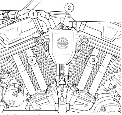
Figure 4-60. Induction module cover: XR 1200X: 1. Fastener, wire form; 2. Fastener, to induction module; 3. Screws (2)
2. Remove screws (3) and the wire form (1) and induction module fastener (2).
3. Carefully rotate induction module cover out of the way.
4. Unplug TMAP sensor harness connector [80B].
5. See Figure 4-61. Remove screw (2).

Figure 4-61. TMAP sensor: XR 1200X: 1. TMAP sensor [80A]; 2. Screw
6. Grasp TMAP sensor (1) and with a gentle twisting motion, pull sensor straight up out of induction module body.
Installation: XR 1200X
| FASTENER | TORQUE VALUE | |
| TMAP sensor screw | 80 in·lbs | 9.0 Nm |
| Induction module coverto cylinder head fastener: XR 1200X | 20-24 ft·lbs | 27.1-32.5 Nm |
| Induction module coverto induction module fastener: XR 1200X | 84-108 in·lbs | 9.5-12.2 Nm |
| Wire form to induction module cover fastener: XR 1200X | 84-108 in·lbs | 9.5-12.2 Nm |
1. If re-using TMAP sensor, inspect O-ring for cuts, tears or signs of deterioration. Replace if necessary.
2. Apply a thin coat of clean engine oil to TMAP sensor Oring.
3. With a gentle twisting motion, insert sensor into induction module with connector [80A] pointing down. Secure sensor to induction module with screw. Tighten to 80 in·lbs (9.0 Nm).
4. Plug sensor harness connector [80B] into TMAP sensor.
5. See Figure 4-60. Install the induction module cover.
- a. Rotate cover between cylinder heads.
- b. Install all fasteners finger-tight.
- c. Verify cover alignment before proceeding.
- d. Tighten socket head screws (3) to 20-24 ft·lbs (27.132.5 Nm).
- e. Tighten fastener (2) to 84-108 in·lbs (9.5-12.2 Nm).
- f. Tighten fastener (1) to 84-108 in·lbs (9.5-12.2 Nm).
6. Install main fuse.
