
Warning! Stop the engine when refueling or servicing the fuel system. Do not smoke or allow open flame or sparks near gasoline. Gasoline is extremely flammable and highly explosive, which could result in death or serious injury.
XL Models: See Figure 4-49.
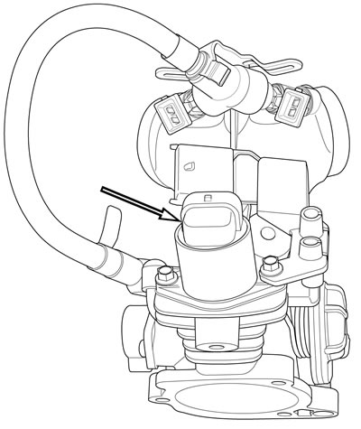
Figure 4-49. IAC: XL models
XR 1200X: See Figure 4-50.
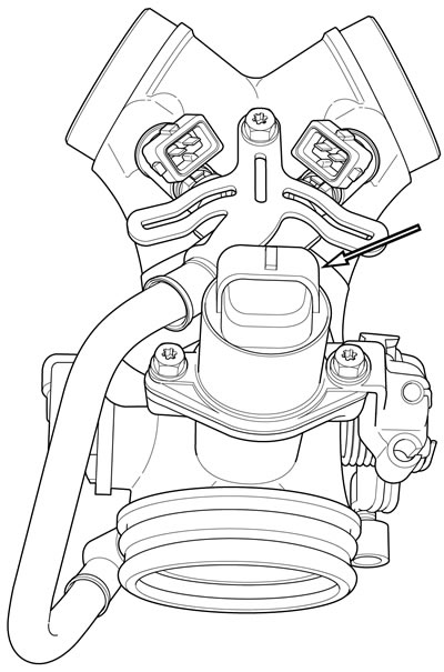
Figure 4-50. IAC: XR 1200X
The ECM uses the IAC to control engine idle speed. See the electrical diagnostic manual.
Removal: XL models
| PART NUMBER | TOOL NAME |
| HD-25070 | HEAT GUN |
Warning! To prevent accidental vehicle start-up, which could cause death or serious injury, remove main fuse before proceeding.
1. Remove main fuse.
2. Remove air cleaner assembly. See 4.3 AIR CLEANER ASSEMBLY.
3. See Figure 4-51. Unplug harness connector [87B] from IAC connector [87A] (1).

Figure 4-51. IAC removal/installation: XL models: 1. IAC Connector [87A]; 2. Screw (2); 3. IAC; 4. Throttle cable bracket
Note. Heat screws (2) to soften the thread sealant and avoid breakage during removal. Use ONLY HEAT GUN (Part No. HD-25070) to heat the screws. NEVER use an open flame.
4. Using a six-point socket (not a Torx wrench), remove two screws (2) in the following order:
- a. Heat fastener nearest to throttle bracket for two minutes using HEAT GUN (Part No. HD-25070). Remove screw.
- b. Heat remaining screw for one minute. Remove screw.
5. See Figure 4-52. Grasp IAC and rotate clockwise until IAC mounting tab (1) clears throttle cable bracket (2).

Figure 4-52. Removing/installing IAC: XL models: 1. IAC mounting tab (2) (rotated 45 degrees); 2. Throttle cable bracket
6. With a gentle twisting motion, pull IAC straight out of induction module body.
Installation: XL models
| FASTENER | TORQUE VALUE | |
| IAC mounting screw: XL models | 60 in·lbs | 6.8 Nm |
1. See Figure 4-53. If re-using IAC (1), inspect O-ring (2) for cuts, tears or signs of deterioration. Replace IAC if O-ring is damaged.
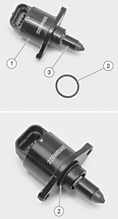
Figure 4-53. IAC and O-ring: 1. IAC; 2. O-ring; 3. Pintle
Warning! Compressed air can pierce the skin and flying debris from compressed air could cause serious eye injury. Wear safety glasses when working with compressed air. Never use your hand to check for air leaks or to determine air flow rates.
2. Clean all locking agent from the threads of the attachment screws and holes. Blow debris from screw holes using low-pressure compressed air.
3. Apply a thin coat of clean engine oil to O-ring.
4. See Figure 4-52. Rotate IAC approximately 45 degrees clockwise so IAC mounting tab will clear throttle cable bracket (2) when IAC is installed.
5. With a gentle twisting motion, insert IAC into induction module.
6. Rotate IAC so that harness connector faces intake manifold and mounting tab is underneath tab on throttle cable bracket.
7. Install IAC.
- a. See Figure 4-51. Apply a drop of LOCTITE 243 MEDIUM STRENGTH THREADLOCKER AND SEALANT (blue) to the threads of each screw (2).
- b. Install two screws (2).
- c. Use a six-point socket (not a Torx wrench). Tighten to 60 in·lbs (6.8 Nm).
8. Plug harness connector [87B] into IAC connector [87A] (1).
9. Install air cleaner assembly. See 4.3 AIR CLEANER ASSEMBLY.
10. Install main fuse.
11. Close left side cover.
Removal: XR 1200X
| PART NUMBER | TOOL NAME |
| HD-25070 | HEAT GUN |
Note. It is not necessary to remove the fuel tank, air box or induction module from the vehicle in order to replace the IAC.
Warning! Gasoline can drain from quick-connect fitting when removing fuel line. Gasoline is extremely flammable and highly explosive, which could result in death or serious injury. Wipe up spilled fuel immediately and dispose of rags in a suitable manner.
1. Purge the fuel supply hose of high pressure gasoline. Disconnect fuel supply hose from fuel pump module. See 4.5 FUELTANK: XR 1200X.
Warning! To prevent accidental vehicle start-up, which could cause death or serious injury, remove main fuse before proceeding.
2. Remove main fuse.
3. See Figure 4-54. Unplug harness connector [87B] from IAC connector [87A] (1).
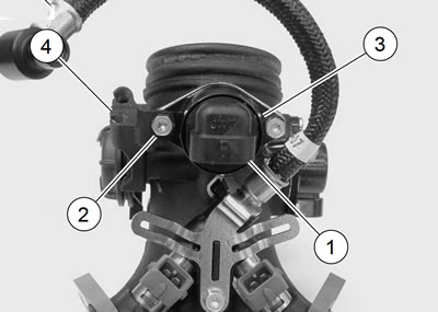
Figure 4-54. IAC removal/installation: XR 1200X: 1. IAC Connector [87A]; 2. Screw (2); 3. IAC; 4. Throttle cable bracket
Note. Screws (2) MUST be heated to soften the thread sealant and avoid breakage during removal. Use ONLY HEAT GUN (Part No. HD-25070) to heatthe screws. NEVER use an open flame.
4. Using a six-point socket (not a Torx wrench), remove two screws (2) in the following order:
- a. Heat fastener nearest to throttle bracket for two minutes using HEAT GUN (Part No. HD-25070). Remove screw.
- b. Heat remaining screw for one minute and remove.
5. See Figure 4-55. Grasp IAC and rotate counterclockwise until IAC mounting tab (1) clears throttle cable bracket (2).
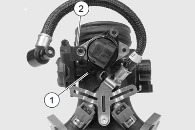
Figure 4-55. Removing/installing IAC: XR 1200X: 1. IAC mounting tab (2) (rotated 45 degrees); 2. Throttle cable bracket
6. With a gentle twisting motion, pull IAC straight out of induction module body.
Installation: XR 1200X
| FASTENER | TORQUE VALUE | |
| IAC mounting screw: XR 1200X | 60 in·lbs | 6.8 Nm |
1. See Figure 4-53. If re-using IAC (1), inspect O-ring (2) for cuts, tears or signs of deterioration. Replace IAC if O-ring is damaged.
Warning! Compressed air can pierce the skin and flying debris from compressed air could cause serious eye injury. Wear safety glasses when working with compressed air. Never use your hand to check for air leaks or to determine air flow rates.
2. Clean all locking agent from the threads of the attachment screws and holes. Blow debris from screw holes using low-pressure compressed air.
3. Apply a thin coat of clean engine oil to O-ring.
4. See Figure 4-55. Rotate IAC approximately 45 degrees counterclockwise so IAC mounting tab will clear throttle cable bracket (2) when IAC is installed.
5. With a gentle twisting motion, insert IAC into induction module.
6. Rotate IAC so that harness connector points straight down and mounting tab is underneath tab on throttle cable bracket.
7. Install the IAC.
- a. See Figure 4-54. Apply a drop of LOCTITE 243 MEDIUM STRENGTH THREADLOCKER AND SEALANT (blue) to the threads of each screw (2).
- b. See Figure 4-54. Install two screws (2).
- c. Use a six-point socket (not a TORX wrench). Tighten to 60 in·lbs (6.8 Nm).
8. Plug harness connector [87B] into IAC connector [87A] (1).
9. Connect fuel hose to fuel pump module. See 4.5 FUEL TANK: XR 1200X.
10. Install main fuse.
11. Close left side cover.
12. Turn on ignition switch and start motorcycle. Carefully check for leaks around fuel hose fitting.