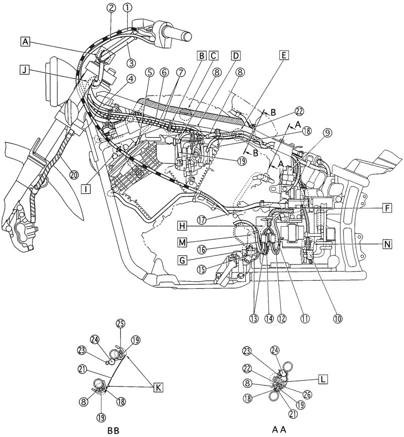
- [A] Fasten the handlebar switch leads (left and right) to the handlebar with plastic locking tie.
- [B] Position the throttle cable and starter cable as shown, and clamp them with holder.
- [C] Clamp the wire harness with the hook of frame side.
- [D] When installing the pipe of throttle cables, press it inside.
- [E] Connect the sensing hose (carburetor joint-AIS side) with a nozzle.
- [F] Push the wire harness inside of the tool box plate.
- [G] Route the sidestand lead inside of engine cover.
- [H] Position the all connectors inside of the connector cover.
- [I] Route the clutch cable through the cable guide.
- [J] Fasten the handlebar switch leads (left and right) under the handle crown with a plastic band. Set the band at four notches, and install it no slacking.
- [K] Route the each hoses through the frame guide and do not pinch it.
- [L] When installing the fitting plate, do not pinch the each hoses and wire harness.
- [M] Fasten the AC magneto lead and sidestand switch lead with a plastic locking tie.
- [N] Fasten the alarm lead with a plastic band on the lid.

1. Clutch cable; 2. Starter cable; 3. Handlebar switch lead (left); 4. Handlebar switch lead (right); 5. High tension code; 6. Starter cable; 7. Throttle cable; 8. Fuel hose (fuel cock-fuel filter); 9. Fuse box; 10. Alarm connector; 11. Fuel pump lead; 12. Speed sensor lead; 13. Sidestand switch lead; 14. Neutral switch lead; 15. Pickup coil lead; 16. AC magneto lead; 17. Ventilation hose; 18. Sensing hose (AIS-carburetor joint); 19. Fuel hose (carburetor-fuel pump); 20. Brake hose; 21. Heat protector; 22. Fuel breather hose (fuel tankroll over valve) (for California); 23. Speedometer lead; 24. Wire harness; 25. Purge hose (carburetor-solenoid valve) (for California); 26 Purge hose (carburetor-solenoid valve) (for California)
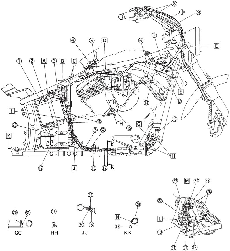
- [A] Clamp the battery positive (+) lead to the battery with battery band.
- [B] Connect the battery negative (-) lead connector and push it into the space between battery box and battery.
- [C] Route the rectifier/regulator lead, wire harness and starter motor positive (+) lead through the outside of frame bracket and fasten them to the frame with a plastic locking tie.
- [D] Connect the purge hose (carburetor side-solenoid valve side) with joint. (for California)
- [E] Route the front turn signal light lead and headlight lead through the rear of headlight body hole.
- [F] Connect the ignition coil lead at red tape to the right side.
- [G] Fasten the rear brake switch lead to the brake switch bracket with a plastic locking tie.
- [H] Fasten the rear brake switch lead and master cylinder reservoir hose to the down tube with a plastic locking tie.
- [I] Fasten the wire harness, starter motor positive (+) lead and battery negative (-) lead to the frame with a plastic locking tie.
- [J] Route the rectifier/regulator lead and carburetor heater lead through inside of battery box hole to outside it and connect them.
- [K] To rear brake caliper
- [L] Clamp the handlebar switch lead (right) and main switch lead to the frame with a holder.
- [M] Arrange the throttle position sensor connector, carburetor heater connector and thermo switch connector between the starting circuit cutoff relay and high tension code.
- [N] Fasten the rear brake switch to the down tube with a plastic locking tie.

1. Battery; 2. Battery positive (+) lead; 3. Starter motor positive (+) lead; 4. Speedometer lead; 5. Fuel hose (carburetor-fuel pump); 6. High tension code; 7. Main switch lead; 8. Throttle cable; 9. Brake hose; 10. Handlebar switch lead (right); 11. Headlight lead; 12. Ignition coil; 13. Master cylinder reservoir hose; 14. Breather hose; 15. Air filter drain hose; 16. Battery negative (-) lead; 17. Rear brake switch lead; 18. Rear brake hose; 19. Carburetor heater connector; 20. Rectifier/regulator; 21. Main switch lead; 22. Flasher relay; 23. Handlebar switch lead (left); 24. Throttle position sensor lead; 25. Carburetor heater lead; 26. Thermo switch lead; 27. Starting circuit cutoff relay; 28. Down tube; 29. High tension code; 30. Purge hose (carburetor solenoid valve) (for California); 31. Carburetor heater lead; 32. Oil level switch lead
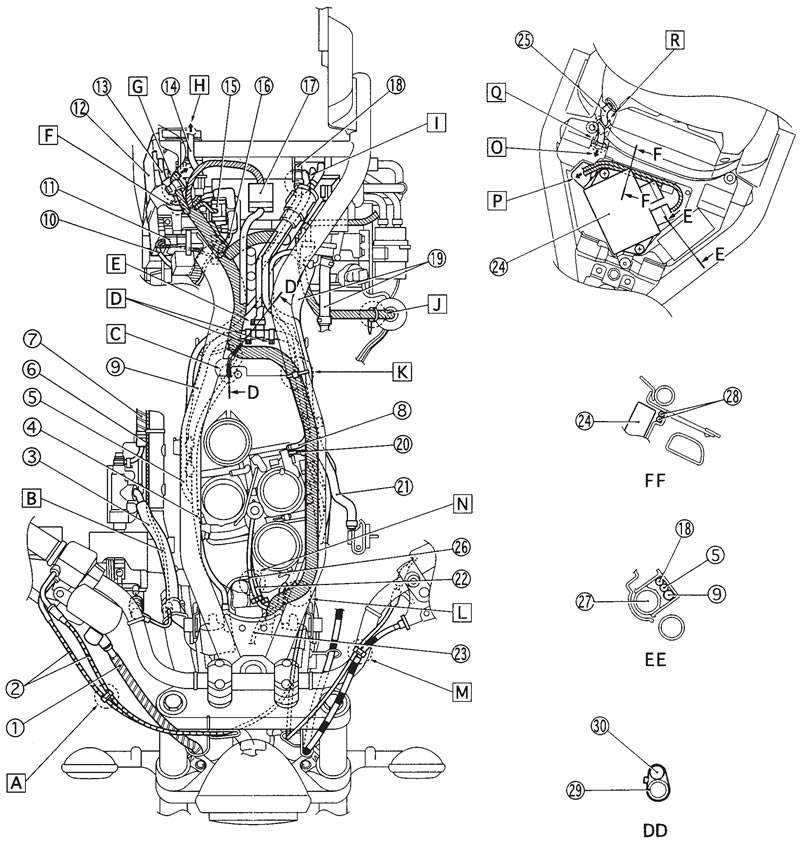
- [A] Clamp the throttle cables with the holder.
- [B] Route the rear brake switch lead under the master cylinder reservoir hose.
- [C] Position the band end of right side bracket.
- [D] Position the steel band end to forward.
- [E] Position the steel band end to right side.
- [F] Route the battery positive (+) lead through the slit of the battery box.
- [G] Clamp the igniter unit lead to the frame with a holder.
- [H] To the rear fender.
- [I] Route the fuel tank breather hose under the fuel filter and connect it (fuel tank side-roll over valve side) with a joint. Position the end of clip outside.
- [J] Fasten the wire harness with a band on the tool box plate.
- [K] Fasten the wire harness to the frame with a plastic locking tie. Position the locking tie front of the solder.
- [L] Route wire harness outside of the guide on the frame.
- [M] Clamp the clutch cable and starter cable with a holder. Position the end of holder down side.
- [N] Route the throttle position sensor lead and carburetor heater lead left side of the tappet cover.
- [O] To the wire harness.
- [P] Route the igniter lead through the igniter plate hole to the wire harness.
- [Q] Clamp the taillight lead with mud guard clamp.
- [R] Clamp the taillight lead with a holder on the mud guard.

1. Brake hose; 2. Throttle cable; 3. Master cylinder reservoir hose; 4. High tension code; 5. Purge hose (carburetor-solenoid valve) (for California); 6. Rear brake switch lead; 7. Brake hose; 8. Sensing hose (AIS-carburetor joint); 9. Fuel hose (carburetor-fuel pump); 10. Battery negative (-) lead; 11. Battery negative (-) lead connector; 12. Battery; 13. Battery positive (+) lead; 14. Taillight lead; 15. Starter relay; 16. Starter motor positive (+) lead; 17. Speedometer lead connector; 18. Fuel tank breather hose (fuel tank-roll over valve) (for California); 19. Ventilation hose; 20. Starter cable; 21. Fuel hose (fuel cock-fuel filter); 22. Carburetor heater lead; 23. Thermo switch lead; 24. Igniter unit; 25. Taillight lead; 26. Throttle position sensor lead; 27. Fuel filter; 28. Igniter unit lead; 29. Frame; 30. Wire harness
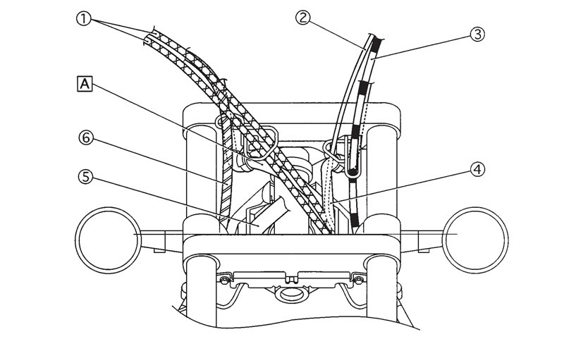
- [A] Route the handlebar switch lead (right) rear side of the throttle cable.

1. Throttle cable; 2. Starter cable; 3. Clutch cable; 4. Handlebar switch lead (left); 5. Headlight lead; 6. Brake hose
