- camshaft sprocket cover
- tappet covers. Refer to "Rear cylinder head."
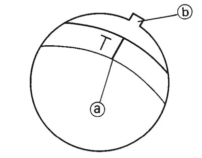
2. Align: "T" mark (a) (with the stationary pointer (b))

a. Temporarily install the AC magneto cover without the pickup coil and stator coil.
b. Turn the crankshaft clockwise.
c. Align the "T" mark (a) with the stationary pointer (b) on the crankcase cover (left) when the rear piston is at TDC on the compression stroke.
d. Check that the rear piston is at TDC in the compression stroke.
e. The rear piston is at TDC on the compression stroke when there is clearance at both of the rocker arms. If there is no clearance then turn the crankshaft clockwise one full turn.
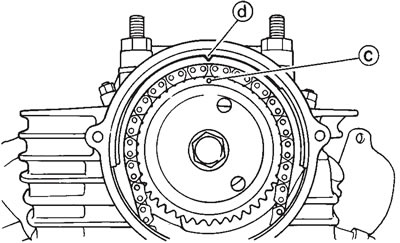
f. When the "T" mark is aligned with the stationary pointer the punch mark (c) on the camshaft sprocket should be aligned with the stationary pointer (d) on the cylinder head.

3. Remove:
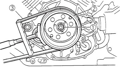
- generator rotor nut (1)
- washer
Note:
- While holding the generator rotor (2) with the sheave holder (3), loosen the generator rotor nut.
- Do not allow the sheave holder to touch the projection on the generator rotor.

- Sheave holder: 90890-01701
4. Remove:
- generator rotor 1 (with the flywheel puller set (2) and adapter (3))
- woodruff key

Note:
- Remove the rotor by pushing back the rotor, the flywheel puller (2) and the adapter (3).
- Install the flywheel puller bolts and tighten the center bolt, making sure that the tool body stays parallel to the rotor. If necessary, one holding bolt may be backed out slightly for realignment of the tool.
- When rotor is removed, the dowel pins and springs are scatter and dropping down. Do not missing them.
- Sheave holder: 90890-01701
- Flywheel puller: 90890-01362
- Adapter: 90890-04131
