| PART NUMBER | TOOL NAME |
| HD-45967 | SHOP DOLLY |
| HD-45968 | FAT JACK |
| HD-46284 | ENGINE HOOK |
Warning! To prevent spray of fuel, purge system of high-pressure fuel before supply line is disconnected. Gasoline is extremely flammable and highly explosive, which could result in death or serious injury.
1. Purge the fuel supply hose of high pressure gasoline. Disconnect fuel supply hose from fuel pump module. See 4.4 FUEL TANK: XL MODELS.
2. Remove seat.
3. Remove left side cover. See 2.18 LEFT SIDE COVER.
Warning! Prevent accidental vehicle start-up, which could cause death or serious injury. First disconnect negative (-) battery cable at engine and then positive (+) cable from battery.
4. Disconnect battery. See 1.22 BATTERY MAINTENANCE.
5. Drain primary chaincase/transmission fluid. See 1.10 TRANSMISSION LUBRICANT.
6. Drain oil tank. See 1.6 ENGINE OIL AND FILTER. Do not install drain plug back in end of drain hose at this time.
7. Remove O2 sensor connectors [137], [138].
8. Remove exhaust pipes and mufflers. See 4.13 EXHAUST SYSTEM: XL MODELS.
9. Remove right front footrest assembly and rear brake linkage.
- a. Models with Mid-mount Controls: See 2.40 RIDER FOOT CONTROLS: XL MID-MOUNT CONTROLS.
- b. Models with Forward Controls: See 2.41 RIDER FOOT CONTROLS: XL FORWARD CONTROLS.
10. Remove screw, washer and exhaust pipe clamp bracket from sprocket cover. Remove two screws securing sprocket cover to engine case. Remove sprocket cover.
11. Loosen rear axle nut and move rear axle all the way forward. Tighten axle nut enough to hold the axle and wheel in position in the rear fork. Remove rear drive belt from transmission sprocket. See 5.6 DRIVE BELT.
12. Remove transmission sprocket. See 5.15 TRANSMISSION SPROCKET.
13. Remove exhaust system interconnect. See 4.13 EXHAUST SYSTEM: XL MODELS.
14. Disconnect oil tank feed, drain and return hoses from oil tank. Pull drain hose up through drain hose sleeve in rear of engine crankcase. Remove hose. See 3.24 OIL TANK.
15. Drain fuel tank. Remove fuel tank. See 4.4 FUEL TANK: XL MODELS.
16. Remove air cleaner assembly.
- a. XL Models except XL 1200V: See 4.3 AIR CLEANER ASSEMBLY, XL Models except XL 1200V.
- b. XL 1200V: See 4.3 AIR CLEANER ASSEMBLY, XL 1200V.
- c. XL 1200X: See 4.3 AIR CLEANER ASSEMBLY, XR 1200X.
- d. EVAP Controlled Models: Remove EVAP purge hose from induction module. See 4.20 EVAPORATIVE EMISSIONS CONTROL.
17. Remove the horn.
- a. Front Mount: See 6.32 HORN, Replacement: Front Mount.
- b. Side Mount: See 6.32 HORN, Replacement: Side Mount.
18. Unplug the following connectors from the induction module:
- a. Fuel injector connectors [84], [85].
- b. TMAP sensor [80].
- c. IAC [87].
- d. TPS [88].
19. Unplug the following electrical connectors from the engine:
- a. Ground wire at powertrain ground stud on crankcase.
- b. Spark plug wires.
- c. Oil pressure switch [120]. See 6.31 OIL PRESSURE SWITCH.
- d. CKP sensor [79]. See 6.22 CRANK POSITION SENSOR (CKP).
- e. Alternator AC connector [46]. See 6.23 VOLTAGE REGULATOR.
- f. Neutral indicator switch connector [136]. See 6.26 NEUTRAL INDICATOR SWITCH.
- g. VSS [65]. See 6.25 VEHICLE SPEED SENSOR (VSS).
- h. Starter relay wire (GN) at starter motor. See 6.10 STARTER.
- i. ET sensor [90]. Cut the barbed cable strap securing sensor harness to ECM caddy. Remove the cable strap. See 4.7 ENGINE TEMPERATURE (ET) SENSOR.
20. Disconnect clutch cable. Remove from clutch lever on left handlebar. Remove cable clips securing clutch cable to frame left front downtube. See 2.29 CLUTCH CONTROL.
21. Remove push-in fastener securing right wire harness caddy to coil bracket. Discard push-in fastener. Remove screw securing ignition switch to coil bracket. Unplug spark plug wires from coil. Unplug ignition coil harness connector [83] from coil. Remove coil and bracket from frame. See 6.13 IGNITION COIL.
22. Remove screw securing left wire harness caddy to right wire harness caddy. Separate caddies. See 6.28 ELECTRICAL CADDIES, Wire Harness Caddy: XL Models.
23. Unplug the following harness connectors located in the wire harness caddies:
- a. Instruments connector [20].
- b. Headlamp connector [38].
- c. Right hand control connector (black) [22].
- d. Left hand control connector (gray) [24].
- e. Front turn signal connector [31].
24. Slide left wire harness caddy between frame and engine, toward right side of vehicle. Move wire harness caddies and wiring harnesses out of the way.
25. Remove induction module and intake manifold as a unit. Secure induction module/intake manifold assembly and throttle cables out of the way. See 4.8 INDUCTION MODULE: XL MODELS.
26. EVAP Controlled Models: Remove EVAP canister and disconnect hoses. See 4.20 EVAPORATIVE EMISSIONS CONTROL.
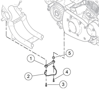
27. See Figure 3-14. Remove screws (3, 4), grounding strap (2), stabilizer link (1) and spacer (5).

Figure 3-14. Rear stabilizer link assembly (typical): 1. Stabilizer link; 2. Grounding strap; 3. Screw; 4. Screw; 5. Spacer
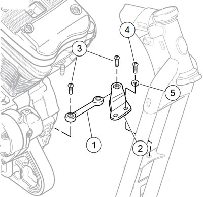
28. See Figure 3-15. Remove upper stabilizer link (2) and brackets (3, 1):
- a. Remove screw (4) securing stabilizer link to engine bracket (1).
- b. Remove screws (5) and washers (8). Remove horn bracket (9) (models with front mounted horn) and upper stabilizer link bracket with stabilizer link.
- c. Remove fasteners (6) and washers (7) and cylinder head bracket (1).

Figure 3-15. Upper front stabilizer link assembly: 1. Engine bracket; 2. Upper stabilizer link; 3. Upper frame bracket; 4. Screw; 5. Screw (2); 6. Screw (2); 7. Lockwasher (2); 8. Washer (2); 9. Horn bracket (front mount models)
29. See Figure 3-16. Remove lower stabilizer link (1) and lower frame bracket (2):
- a. Remove screw (3) securing stabilizer link to engine crankcase boss.
- b. Remove screws (4), washers (5) and lower frame bracket with stabilizer link.

Figure 3-16. Lower front stabilizer link assembly (typical): 1. Lower stabilizer link; 2. Lower frame bracket; 3. Screw (2); 4. Screw (2); 5. Washer (2)
30. Remove rider left footrest and mounting bracket assembly and shift lever.
- a. Models with Mid-mount Controls: See 2.40 RIDER FOOT CONTROLS: XL MID-MOUNT CONTROLS.
- b. Models with Forward Controls: See 2.41 RIDER FOOT CONTROLS: XL FORWARD CONTROLS.
31. Models with Passenger Footrests: Remove left passenger footrest and mounting bracket assembly. See 2.43 PASSENGER FOOTRESTS.
Note. Keep reservoir upright. If the reservoir is inverted, bleed the rear brake. See 2.17 BLEEDING BRAKES.
32. Remove rear brake master cylinder remote reservoir. Do not disconnect hose from reservoir. Secure reservoir upright, out of the way. See 2.13 REAR BRAKE MASTER CYLINDER RESERVOIR.
33. Remove rear stop lamp switch from battery tray. Unplug rear stop lamp switch connectors [121].
34. Remove screw and P-clamp securing rear brake hose to battery tray.
35. Pull rear stop lamp switch and brake lines out of the way. Be careful not to bend or kink metal brake lines. See 6.21 REAR STOP LAMP SWITCH.
36. With the aid of a FAT JACK (Part No. HD-45968), support motorcycle on SHOP DOLLY (Part No. HD-45967).
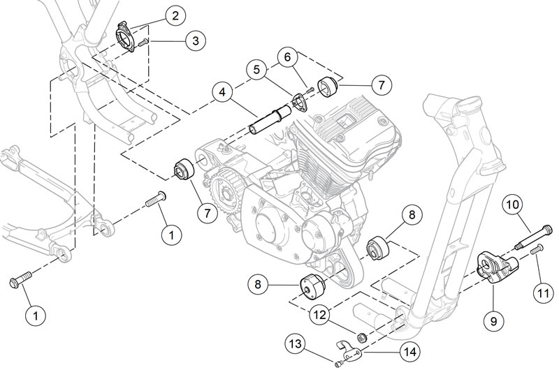
37. See Figure 3-17. Remove fasteners (13) and J-clip (14) from each side of frame.

Figure 3-17. Engine mount/isolator components (typical): 1. Bolt (2); 2. Rear isolator mount; 3. Screw (2); 4. Rear fork pivot shaft; 5. Rear pivot lockplate; 6. Screw (3); 7. Rear isolator (2); 8. Front isolator (2); 9. Front isolator mount; 10. Front mount bolt; 11. Screw (2); 12. Nut; 13. Screw; 14. J-clip (2)
38. Loosen, but do not remove, two front isolator mounting bracket screws (11) on left side of engine.
39. Loosen, but do not remove, two rear isolator mounting bracket screws (3) on left side of engine.
40. Attach ENGINE HOOK (Part No. HD-46284) and engine hoist. Carefully raise engine enough to relieve pressure from mounting bolts.
41. Remove front engine mount bolt (10) and nut (12).
42. Remove two screws (11) and front isolator mount (9).
43. Remove two rear engine mount/rear fork pivot bolts (1). Pull rear fork back until fork pivot bosses clear the frame.
44. Remove oil tank vent hose from oil tank. See 3.24 OIL TANK.
45. Remove two screws (3) and rear isolator mounting bracket (2) from frame.
46. Lift engine as necessary and swing assembly out from chassis toward the left side. Swing rear of engine out first. Then remove engine from chassis.
