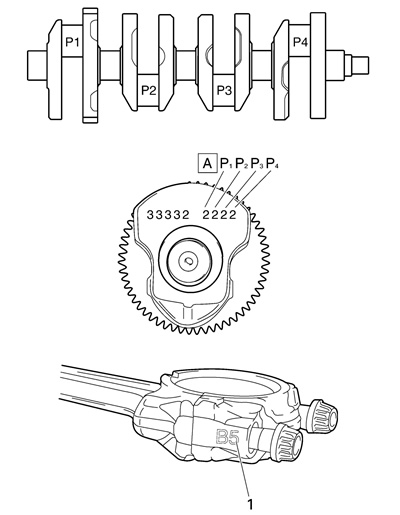
- Crankshaft-pin-to-big-end-bearing clearance
Out of specification → Replace the big end bearings.
Crankshaft-pin-to-big-end-bearing clearance: 0.034-0.058 mm (0.0013-0.0023 in)
Limit: 0.09 mm (0.0035 in)
The following procedure applies to all of the connecting rods.
Caution! Do not interchange the big end bearings and connecting rods. To obtain the correct crankshaft-pin-to-big-end-bearing clearance and prevent engine damage, the big end bearings must be installed in their original positions.
a. Clean the big end bearings, crankshaft pins, and the inside of the connecting rods halves.
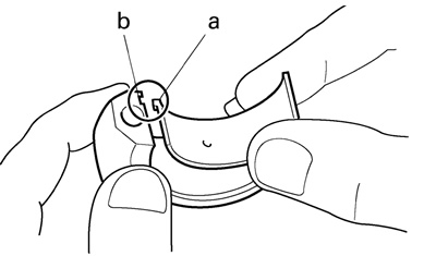
b. Install the big end upper bearing into the connecting rod and the big end lower bearing into the connecting rod cap.
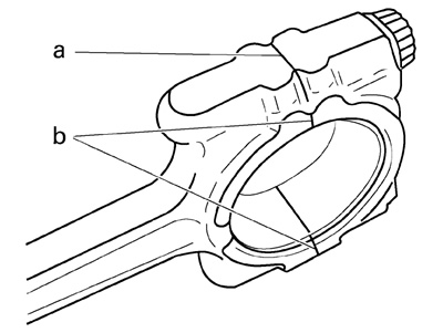
Note: Align the projections «a» on the big end bearings with the notches «b» in the connecting rod and connecting rod cap.
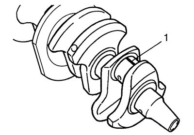
c. Put a piece of Plastigauge® «1» on the crankshaft pin.
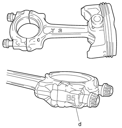
d. Assemble the connecting rod halves.
Notes:
- Do not move the connecting rod or crankshaft until the clearance measurement has been completed.
- Lubricate the bolt threads with molybdenum disulfide grease.
- Make sure that the «Y» mark «c» on the connecting rod faces towards the left side of the crankshaft.
- Make sure that the characters «d» on both the connecting rod and connecting rod cap are aligned.
e. Tighten the connecting rod bolts.
Note: Install by carrying out the following procedures in order to assemble in the most suitable condition.
Connecting rod bolt: 29.4 Nm (3.0 m·kg, 21 ft·lb)
Notes:
- First, tighten the bolts to 15 Nm (1.5 mrkg. 11 ft·lb).
- Retighten the bolts to 29.4 Nm (3.0 mrkg. 21 ft·lb).
f. Replace the connecting rod bolts with new ones.
g. Clean the connecting rod bolts.
h. After installing big end bearing, assemble the connecting rod and connecting rod cap once using a single unit of the connecting rod.
i. Tighten the connecting rod bolt while checking that the sections shown «a» and «b» are flush with each other by touching the surface.
- Side machined face «a»
- Thrusting faces (4 places at front and rear) «b»
Note: To install the big end bearing. care should be taken not to install it at an angle and the position should not be out of alignment.
j. Loosen the connecting rod bolt, remove the connecting rod and connecting rod cap and install these parts to the crankshaft with the big end bearing kept in the current condition.
k. Tighten the connecting rod bolts.
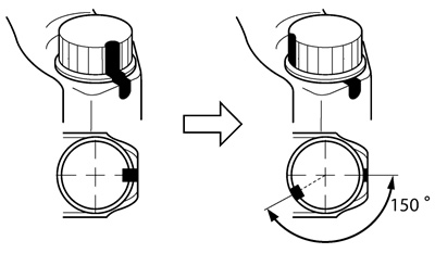
Connecting rod bolt: 20 Nm (2.0 m·kg, 14 ft·lb) + 150°.
Caution! Tighten the connecting rod bolts using the plastic-region tightening angle method.
l. Clean the connecting rod bolts.
m. Tighten the connecting rod bolts.
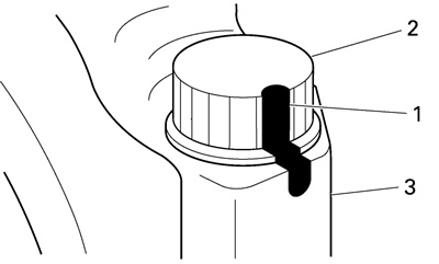
n. Put a mark «1» on the corner of the connecting rod bolt «2» and the connecting rod
o. Tighten the bolt further to reach the specified angle (150°).
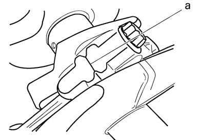
p. After the installation, check that the section shown «a» is flush with each other by touching the surface.
- Side machined face «a»
Warnings!
- When the bolt is tightened more than the specified angle, do not loosen the bolt and then retighten it.
- Replace the bolt with a new one and perform the procedure again.
- If they are not flush with each other, remove the connecting rod bolt and big end bearing and restart from step «e». In this case, make sure to replace the connecting rod bolt.
Cautions!
- Do not use a torque wrench to tighten the nut to the specified angle.
- Tighten the bolt until it is at the specified angles.
q. Remove the connecting rod and big end bearings.
Refer to «Removing the connecting rods and pistons».
r. Measure the compressed Plastigauge® width on the crankshaft pin. If the crankshaft-pin-to-big-end-bearing clearance is out of specification, select replacement big end bearings.

2. Select:
- Big end bearings (P1-P4)
Notes:
- The numbers «A» stamped into the crankshaft wed and the numbers «1» on the connecting rods are used to determine the replacement big end bearings sizes.
- «P1»-«P4» refer to the bearings shown in the crankshaft illustration.
For example, if the connecting rod «P1» and the crankshaft web «P1» numbers are «5» and «2» respectively, then the bearing size for «P1» is:
«P1» (connecting rod) - «P1» (crankshaft) = 5 - 2 = 3 (brown)
| BIG END BEARING COLOR CODE | |
| 1 | Blue |
| 2 | Black |
| 3 | Brown |
| 4 | Green |
