
Removal
1. Separate the crankcase halves (refer to Section 23).
2. Lift the crankshaft out of the left-hand crankcase half (see illustration). If it appears stuck, tap it gently using a soft-faced mallet.
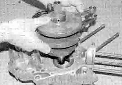
27.2. Lift the crankshaft out of the crankcase
3. If required, remove the connecting rods from the crankshaft (see Section 28).
Inspection
4. Clean the crankshaft with solvent, using a rifle-cleaning brush to scrub out the oil passages. If available, blow the crank dry with compressed air. and also blow through the oil passages. Check the cam chain sprockets for wear or damage. If any of the sprocket teeth on the left-hand end are excessively worn, chipped or broken, the crankshaft must be replaced with a new one.
5. Refer to Section 26 and examine the mam bearings (see illustration). If they are scored, badly scuffed or appear to have been seized, new bearings must be installed. Always replace the main bearings as a set. If they are badly damaged, check the corresponding crankshaft journal. Evidence of extreme heat, such as discoloration, indicates that lubrication failure has occurred. Be sure to thoroughly check the oil pump and pressure relief valve as well as all oil holes and passages before reassembling the engine.

27.5. Check the main bearings as described
6. Inspect the crankshaft journals, paying particular attention where damaged bearings have been discovered. If the journals are scored or pitted in any way a new crankshaft will be required. Note that undersizes are not available, precluding the option of re-grinding the crankshaft.
7. Place the crankshaft on V-blocks and check the runout at the main bearing journals using a dial gauge. Compare the reading to the maximum specified at the beginning of the Chapter. If the runout exceeds the limit, the crankshaft must be replaced.
Oil clearance check
8. Whether new bearing shells are being fitted or the original ones are being re-used, the main bearing oil clearance should be checked prior to reassembly.
9. Using a Vernier caliper, measure the diameter of the crankshaft main bearing journals (see illustration) Using a bore gauge and micrometer, measure the internal diameter of the main bearings (see illustration). Calculate the difference between the two to determine the main bearing oil clearance and compare the results to the specifications at the beginning of the Chapter. If the oil clearance exceeds the service limit, new main bearings must be selected and installed.
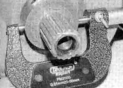
27.9a. Measure the diameter of the main journal...

27.9b ...and the internal diameter of the main bearing
Main bearing selection
10. Replacement main bearings are supplied on a selected fit basis. Remove the old bearings from the crankcases (see below). Using a bore gauge and micrometer, measure the internal diameter of the bearing housing in each crankcase half and record them. Also note the crankshaft main journal size number, as marked on the crankshaft web adjacent to the journal (see illustration 24.13a) To select the correct bearing for a particular journal and housing size, use the table below and crossrefer the journal size number (stamped on the crank web) with the housing size as measured to determine the colour code of the bearing required.
Main bearing replacement
11. Replacement of the main bearings requires the use of a hydraulic press In order to avoid damaging either the crankcase or the new bearings. It is therefore advised that replacement is undertaken by a Honda dealer or a suitably equipped specialist. Note that there is a tab on the main bearing which must align with the groove in the housing rim (see illustration). Apply molybdenum disulphide oil (a mixture of 50% molybdenum disulphide grease and 50% engine oil) to the outside of the bearing to ease its entry into the housing.
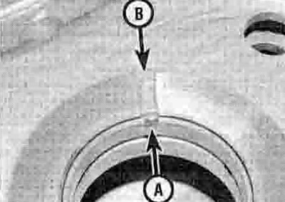
27.11. Align the tab (A) with the groove (B)
Crankshaft selection
12. If a new crankshaft Is required, the replacement is selected according to the crankcase main bearing size - this is so that the correct oil clearance is maintained. Code numbers and letters stamped on the crankshaft and crankcase are used to identify the correct replacement. Each crankshaft main bearing journal size number is stamped on the outside crankshaft web adjacent to the journal, and will be either a 1 or a 2 (see illustration 24.13a). The corresponding main bearing size letter is stamped into the appropriate crankcase half adjacent to the bearing housing and will be either an A or a В (see illustration 24.13b). If the main bearing size is coded A. the corresponding crankshaft journal must be coded 1. If the main bearing size is coded B. the corresponding crankshaft journal must be coded 2.
Installation
13. If removed, fit the connecting rods onto the crankshaft (see Section 28).
14. Apply molybdenum disulphide oil (a mixture of 50% molybdenum disulphide grease and 50% engine oil) to the main bearings (see illustration) Carefully lower the tapered (alternator) end of the crankshaft into 2 position in the left-hand crankcase (see illustration 27.2).
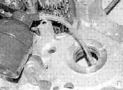
27.14. Lubricate the main bearings before installing the crankshaft
15. Reassemble the crankcase halves (see Section 23).
| XL models | Main bearing journal code | |
| Main bearing housing size | 1 - (44.992 to 45.000 mm) | 2 - (44.984 to 44.991 mm) |
| 48.990 to 49.000 mm | C - Brown | В - Black |
| 49.000 to 49.010 mm | В - Black | A - Blue |
| XRV models | Main bearing journal code | |
| Main bearing housing size | 1 - (49.992 to 50.000 mm) | 2 - (49.984 to 49.991 mm) |
| 53.970 to 53.980 mm | C - Brown | В - Black |
| 53.980 to 53.990 mm | В - Black | A - Blue |