
1. Measure the bearing to crankshaft journal clearance as follows:
Note: Do not turn the connecting rods and crankshaft during the clearance measurement as this will damage the Plastigauge. The crankshaft journal clearances are measured using Plastigauge (Triumph part number 3880150-T0301).
2. Separate the crankcase halves (see Crankcases - removal).
3. Wipe the exposed areas of the crankshaft journals, and the bearing face inside the cap.
4. Apply a thin smear of grease to the journals and a small quantity of silicone release agent to the bearings.
5. Trim a length of the Plastigauge to fit across each journal. Fit the strip to the journal using the grease to hold the Plastigauge in position.
Note: The original fixings may be reused for bearing selection. Do not use new fixings as they may only be used once, even if the single use is related to bearing selection.
6. Lubricate the threads and the face of the fixings with molybdenum disulphide grease. Refit the crankcase and tighten the original fixings (see Crankcases - assembly).
7. Release the fixings and remove the crankcase.
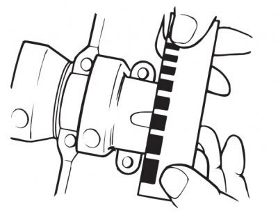
8. Using the Plastigauge kit, measure the width of the compressed Plastigauge.
Checking the measured clearance
9. For specifications refer to Crankshaft.
10. If the clearance exceeds the service limit, measure the diameter of the crankshaft bearing journal.
Note: If any journal has worn beyond the service limit, the crankshaft must be replaced. Due to the techniques used during manufacture, the crankshaft cannot be reground and oversize bearings are not available.
Main bearing selection
Note: Minor differences in dimensions are compensated for by using selective bearings. For further information on bearing part number to colour cross-references, see the latest parts information.
1. Select the correct bearings as follows:
2. Measure and record the diameter of each crankshaft bearing journal.
3. Measure and record each bearing bore diameter in the crankcase (bearings removed, journal caps fitted and all fixings fully torqued).
4. Select and install the correct bearings by matching the information found in the main bearing selection chart.
5. Install the new bearings.
Main bearing selection chart
| Shell Colour | Crankcase Bore | Crankshaft Journal Diameter | Running Clearance |
| White | 37.984 to 37.975 | 35.000 to 34.993 | 0.033 to 0.011 |
| Red | 37.984 to 37.975 | 34.992 to 34.984 | 0.034 to 0.011 |
| Red | 37.993 to 37.985 | 35.000 to 34.993 | 0.035 to 0.013 |
| Blue | 37.993 to 37.985 | 34.992 to 34.984 | 0.035 to 0.013 |
| For instance: | |
| Crankcase Bore | 37.978 mm |
| Crankshaft Journal Diameter | 34.988 mm |
| Required Bearing | Blue |
Warning! Always confirm, using the Plastigauge method, that the running clearance is correct before final assembly. Severe engine damage could result from incorrect clearance resulting in loss of motorcycle control and an accident.
Note:
- Repeat the measurements for all respective journals.
- It is normal for the bearings selected to differ from one journal to another.
- It is also normal for there to be two options of bearing shell colour. In such cases, pick the shell size that gives the greater running clearance.
Crankshaft end float
1. For specifications refer to Crankshaft.
Note: Crankshaft end float is controlled by the tolerances in crankshaft and crankcase machining. No thrust washers are used. If the crankshaft end float is outside the specified limit, the crankshaft and/or the crankcases must be replaced.