
General
Warning! Never bend belt forward into a loop smaller than the drive sprocket diameter. Never bend belt into a reverse loop. Over bending can damage belt resulting in premature failure, which could cause loss of control and death or serious injury.
In the case of stone damage to belt, inspect the sprockets for damage and replace as required. If replacing belt, always replace both transmission and rear sprockets.
Cleaning
Keep dirt, grease, oil, and debris off the drive belt and sprockets. Clean the belt with a rag slightly dampened with a light cleaning agent.
Inspection
Sprockets
Note. Chrome chips or rear sprocket gouges large enough to be harmful will leave a pattern on the belt face.

Figure 1-28. Rear Sprocket: 1. Tooth; 2. Groove
1. See Figure 1-28. Inspect each tooth (1) of rear sprocket for:
- a. Tooth damage.
- b. Large chrome chips with sharp edges.
- c. Gouges caused by hard objects.
- d. Excessive loss of chrome plating (see next step).
2. To check if chrome plating has worn off, drag a scribe or sharp knife point across the bottom of a groove (2) (between two teeth) with medium pressure.
- a. If scribe or knife point slides across groove without digging in or leaving a visible mark, chrome plating is still good.
- b. If scribe or knife points digs in and leaves a visible mark, it is cutting the bare aluminum. A knife point will not penetrate the chrome plating.
3. Replace rear sprocket if major tooth damage or loss of chrome exists.
Idler pulley: XR 1200X
See Figure 1-29. Inspect idler pulley for signs of uneven wear. Excessive lateral side play of 0.035 in (0.9 mm) or roughness indicates worn bearings. Replace idler pulley as an assembly. See 5.6 DRIVE BELT.
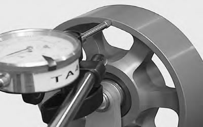
Figure 1-29. Measuring Lateral Side Play on Idler Pulley
Drive belt
Note. Belt teeth are coated with polyethylene lubricant. Coating will wear off over time. This is not an indicator of belt wear.

Figure 1-30. Drive Belt Wear Patterns
See Figure 1-30. Inspect drive belt for:
- Cuts or unusual wear patterns.
- Outside edge bevelling (8). Some bevelling is common, but it indicates that sprockets are misaligned.
- Stone punctures (7) on outside ribbed surface. If cracks/damage exists near edge of belt, replace belt immediately. Damage to center of belt will require belt replacement eventually. When cracks extend to the edge of the belt, failure is imminent.
- Inside (toothed portion) of belt for exposed tensile cords (normally covered by nylon layer and polyethylene layer). This condition will result in belt failure and indicates worn transmission sprocket teeth. Replace belt and transmission sprocket.
- Signs of puncture or cracking at the base of the belt teeth. Replace belt if either condition exists.
- If conditions 2, 3, 6 or 7 (on edge of belt) exist, replace belt.
Note. Condition 1 may develop into 2 or 3 over time. Condition 1 is not grounds for replacing the belt, but it should be watched closely before condition 2 develops which will require belt replacement.
Table 1-12. Drive belt wear analysis
| №.* | CONDITION | REQUIRED ACTION |
| 1 | Internal tooth cracks (hairline) | OK to run, but monitor condition. |
| 2 | External tooth cracks | Replace belt. |
| 3 | Missing teeth | Replace belt. |
| 4 | Chipping (not serious) | OK to run, but monitor condition. |
| 5 | Fuzzy edge cord | OK to run, but monitor condition. |
| 6 | Hook wear | Replace belt and sprocket. |
| 7 | Stone damage | Replace belt if damage is on the edge. |
| 8 | Bevel wear (outboard edge only) | OK to run, but monitor condition. |
| XR only | Excess edge wear | Check idler bearings and bracket attachment. |
* See Figure 1-30.
Drive belt deflection
| PART NUMBER | TOOL NAME |
| HD-35381A | BELT TENSION GAUGE |
| FASTENER | TORQUE VALUE | |
| Axle, rear, nut | 95-105 ft·lbs | 129-142 Nm |
| Brake hose clamp to rear fork screw | 30-40 in·lbs | 3.4-4.5 Nm |
Gauging deflection
Check belt deflection at the loosest spot in the belt with the transmission in neutral and the motorcycle at ambient temperature.
1. With the motorcycle unladen and resting on its jiffy stand, fit the BELT TENSION GAUGE (Part No. HD-35381A) on the belt.
- a. XL Models: See Figure 1-31. Position the gauge halfway between the transmission and rear wheel sprockets.
- b. XR 1200X: See Figure 1-32. Fit the tension gauge half-way (1) between the idler wheel and rear sprocket.
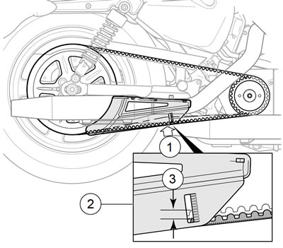
Figure 1-31. Belt Deflection: XL Models: 1. 10 lb (4.5 kg); 2. Deflection gauge; 3. Graduations 1/8 in (3.2 mm)

Figure 1-32. Belt Deflection: XR 1200X: 1. 10 lb (4.5 kg); 2. Deflection gauge; 3. Graduations 1/8 in (3.2 mm)
2. With the BELT TENSION GAUGE set to 0 lb (0 kg), note the current belt position.
- a. XL Models: See Figure 1-31. View position through window on drive belt guard.
- b. XR 1200X: See Figure 1-32. Check position (2) on front of debris deflector.
3. Using the BELT TENSION GAUGE, apply 10 lb (4.5 kg) of force to the bottom belt.
4. Count the number of gradations (3) between the original belt position and after applying the force. Multiply this number by 1/8 in (3.2 mm) to determine the deflection.
5. Compare the deflection to specifications. Refer to Table 1-13.
6. Adjust as necessary.
Warning! Be sure wheel and brake caliper are aligned. Riding with a misaligned wheel or brake caliper can cause the brake disc to bind and lead to loss of control, which could result in death or serious injury.
Note. When gauging deflection, check the rear brake caliper position on rear brake disc. Disc should run true within brake caliper.
Table 1-13. Belt deflection specifications*
| MODELS | in | mm |
| XL 883R | 9/16-5/8 | 14.3-15.9 |
| Other XL models | 1/4-5/16 | 6.4-7.9 |
| XR 1200X | 1/4-3/8 | 6.4-9.5 |
* Deflection measured at 10 lb (4.5 kg) tension.
Adjustment
Note. Rear brake line is clamped tightly to rear fork to avoid chafing of brake line in clamp. A small amount of slack must be maintained in rear brake line between clamp and rear caliper when rear wheel is adjusted.
1. XL Models: See Figure 1-33. Remove screw (4) from clamp (3) on rear brake line (2).
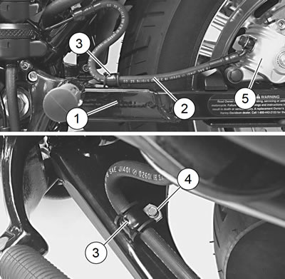
Figure 1-33. Rear Brake Line: XL Models: 1. Rear fork; 2. Rear brake line; 3. Clamp; 4. Screw; 5. Rear brake caliper
2. See Figure 1-34. Remove and discard E-clip (1) and loosen rear axle nut (4).
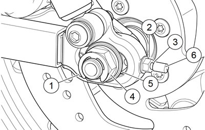
Figure 1-34. Drive Belt Adjustment: XL Models: 1. E-clip; 2. Axle adjuster nut (2); 3. Axle adjuster (2); 4. Axle nut; 5. Washer; 6. Protective cap (2)
Note. Turn both adjuster nuts the same number of turns in order to maintain approximate alignment of rear wheel.
3. Turn axle adjuster nuts (2) on each side of rear fork clockwise to decrease belt deflection (increase tension), or counterclockwise to increase belt deflection (decrease tension).
4. Check rear wheel alignment. See 1.24 WHEEL ALIGNMENT, Wheel Alignment.
Warning! Do not exceed specified torque when tightening axle nut. Exceeding torque can cause wheel bearings to seize during vehicle operation, which could result in death or serious injury.
5. After belt deflection and wheel alignment are properly adjusted,
- a. Tighten axle nut (4) to 95-105 ft·lbs (129-142 Nm). Install new E-clip (1).
- b. XL Models: See Figure 1-33. Reposition clamp (3) on rear brake line (2) and secure clamp to rear fork (1) with screw (4). Tighten to 30-40 in·lbs (3.4-4.5 Nm).