
Removal
Warning! Prevent accidental vehicle start-up, which could cause death or serious injury. First disconnect negative (-) battery cable at engine and then positive (+) cable from battery.
1. Disconnect battery. See 1.22 BATTERY MAINTENANCE.
2. Drain transmission lubricant and remove primary cover. See 5.3 PRIMARY COVER.
3. Remove rear muffler and exhaust pipe. See 4.13 EXHAUST SYSTEM: XL MODELS or 4.14 EXHAUST SYSTEM: XR 1200X.
4. Remove the starter solenoid connector [128].
5. Remove positive (+) battery lead and solenoid wire from starter.
Note. A ball hex driver may be required to gain access to the starter mounting bolts.
6. See Figure 6-18. Remove the two starter mounting bolts and washers.
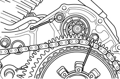
Figure 6-18. Starter mounting bolts
7. XL Models: Remove fastener securing oil line retaining clamp to starter.
8. Remove starter and gasket from right side of motorcycle.
Touch-up paint
Touch up damaged paint before installation. Follow the directions provided with the touch-up paint. Paint flaking does not require starter replacement.
Installation
| FASTENER | TORQUE VALUE | |
| Starter mounting bolt | 13-20 ft·lbs | 17.6-27.1 Nm |
| Starter motor oil line clamp fastener | 16-21 in·lbs | 1.8-2.4 Nm |
| Starter positive terminal nut | 60-85 in·lbs | 6.8-9.6 Nm |
1. Install starter and starter gasket from right side of motorcycle.
2. See Figure 6-18. Install two starter mounting bolts and washers. Tighten to 13-20 ft·lbs (17.6-27.1 Nm).
3. XL Models: Install oil line clamp to starter motor. Tighten to 16-21 in·lbs (1.8-2.4 Nm).
4. Connect the starter solenoid connector [128].
5. Install positive (+) battery cable and solenoid wire to solenoid stud. Tighten to 60-85 in·lbs (6.8-9.6 Nm). Place rubber boot securely over terminal.
6. Install primary cover. See 5.3 PRIMARY COVER.
7. Fill primary chaincase/transmission with proper lubricant. See 1.10 TRANSMISSION LUBRICANT.
8. Install rear exhaust pipe and muffler. See 4.13 EXHAUST SYSTEM: XL MODELS or 4.14 EXHAUST SYSTEM: XR 1200X.
Warning! Connect positive (+) battery cable first. If positive (+) cable should contact ground with negative (-) cable connected, the resulting sparks can cause a battery explosion, which could result in death or serious injury.
9. Connect battery. See 1.22 BATTERY MAINTENANCE.
Solenoid
| FASTENER | TORQUE VALUE | |
| Solenoid contact post jamnut | 65-80 in·lbs | 7.3-9.0 Nm |
| Starter ring terminal hex nut | 60-80 in·lbs | 6.8-9.0 Nm |
Cover and plunger removal
1. See Figure 6-19. Remove fasteners (1), cover (2) and gasket (3).
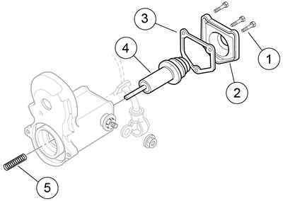
Figure 6-19. Soleniod plunger: 1. Fasteners; 2. Cover; 3. Gasket; 4. Plunger; 5. Spring
2. Remove the plunger (4) with spring (5).
Short post contact: starter
1. Disassemble the short post contact:
- a. Remove the hex nut and the ring terminal from the post.
- b. See Figure 6-20. Remove jamnut (8), wave washer (7), O-ring (6) and round bushing (5):
- c. Remove the post bolt (1).
- d. Remove the hold-in terminal (2) from the post bolt.
- e. Remove the contact plate (3) and the square bushing (4).
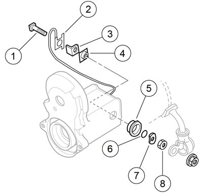
Figure 6-20. Short post contact (starter): 1. Post bolt; 2. Hold-in terminal; 3. Contact plate; 4. Square bushing; 5. Round bushing; 6. O-ring; 7. Wave washer; 8. Jamnut
2. Assemble the short post contact:
- a. Insert the square bushing into the housing.
- b. Install the contact plate with the 90 degree part of the contact plate against the solenoid winding.
- c. Install the post bolt through the hold-in terminal, the contact plate and the square bushing.
- d. Install the round bushing, O-ring, wave washer and jamnut.
Long post contact: battery positive
1. See Figure 6-21. Remove the long post contact:
- a. Remove hex nut (9).
- b. Remove jamnut (8), wave washer (7), O-ring (6) and the round bushing (5).
- c. Remove post bolt (4), contact plate (3), square bushing (2) and paper insulator (1).

Figure 6-21. Long post contact (battery): 1. Paper insulator; 2. Square bushing; 3. Contact plate; 4. Post bolt; 5. Round bushing; 6. O-ring; 7. Wave washer; 8. Jamnut; 9. Hex nut
2. Install the long post contact:
- a. Insert the square bushing through the paper insulator into the housing.
- b. Install the contact plate with the foot against the solenoid winding.
- c. Install the post bolt.
- d. Install the round bushing, O-ring, wave washer and jamnut.
Note. Check that the index pin on the round bushing fits the blind hole in the housing.
Plunger and cover installation
1. Apply LUBRIPLATE 110 to the plunger shaft. Install the spring.
2. Install the plunger and spring in the housing.
3. While compressing the plunger, alternately tighten the contact post jamnuts to 65-80 in·lbs (7.3-9.0 Nm).
4. Check that the contact plates are aligned to the solenoid winding.
5. Install the cover:
- a. Install a new gasket on the cover.
- b. Install the cover.
- c. Install the fasteners until snug.
6. Install the starter ring terminal.
7. Install the hex nut. Tighten to 60-80 in·lbs (6.8-9.0 Nm).
Clutch shaft assembly
Removal
1. See Figure 6-22. Loosen the two long starter support bolts (1).
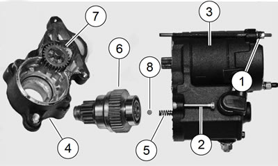
Figure 6-22. Starter drive housing and clutch shaft: 1. Starter support bolts; 2. Fasteners; 3. Starter/solenoid housing; 4. Clutch assembly housing; 5. Spring; 6. Clutch shaft assembly; 7. Idler gear; 8. Steel ball
2. Remove the two fasteners (2) and separate the clutch assembly housing (4) from the starter/solenoid housing (3).
3. Save the spring (5) from the solenoid plunger shaft.
Note. Remove the old assembly lube to release the steel ball (8).
4. Remove and save the steel ball from the bearing end of the clutch shaft assembly (6) bore.
5. Tap on the end of the shaft to remove the clutch shaft assembly from the housing.
6. Remove the idler gear (7) from the bearing cage.
7. Remove bearing cage and the five steel cylinders.
Inspection
1. Inspect the O-rings in the clutch assembly housing bore.
2. Inspect the spring for kinks or elongation.
3. Inspect the steel ball.
4. Inspect the idler gear and the cage.
5. Inspect the clutch shaft assembly pinion gear for missing or damaged teeth.
6. Check that the roller bearings and the clutch gear on the clutch shaft rotate freely.
Installation
1. Lubricate components with LUBRIPLATE 110.
2. See Figure 6-23. Install the bearing cage (1) with the five steel cylinders (2).
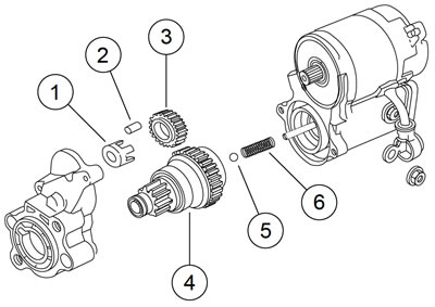
Figure 6-23. Starter clutch assembly: 1. Bearing cage; 2. Steel cylinders; 3. Idler gear; 4. Clutch shaft assembly; 5. Steel ball; 6. Spring
3. Install the idler gear (3) over the bearing cage.
4. Match the gear teeth to the idler gear and install the clutch assembly (4) in the housing. Seat the bearing in the counterbore.
5. Install the steel ball (5) in the bore of the shaft.
6. Apply a light film of LUBRIPLATE 110 to solenoid plunger shaft. Install return spring (6) on solenoid plunger shaft.
7. Apply a thin layer of HARLEY-DAVIDSON HIGH PERFORMANCE SEALANT - GRAY to the face of the clutch assembly housing.
8. Fit the clutch assembly housing to the starter/solenoid housing to the clutch assembly housing.
9. Install the fasteners and alternately tighten until snug.