
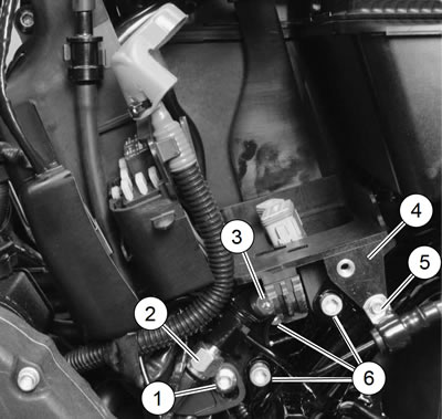
Figure 6-16. Battery tray assembly: 1. ECM caddy fastener; 2. Rear stop lamp switch assembly; 3. TORX fastener; 4. Battery tray; 5. Brake line clamp fastener; 6. Battery tray fastener
Removal
Warning! Prevent accidental vehicle start-up, which could cause death or serious injury. First disconnect negative (-) battery cable at engine and then positive (+) cable from battery.
1. Remove battery. See 1.22 BATTERY MAINTENANCE.
2. Unplug and remove TSM/TSSM/HFSM. See 6.7 TURN SIGNAL AND SECURITY MODULE (TSM/TSSM/HFSM).
3. XL Models: see Figure 6-16. Position rear stop lamp switch as follows:
- a. Remove rear brake master cylinder reservoir cover.
- b. Secure the reservoir out of the way. See 2.13 REAR BRAKE MASTER CYLINDER RESERVOIR.
- c. Remove brake line clamp fastener (5) from battery tray (4).
- d. Remove TORX fastener (3) securing rear stop lamp switch assembly (2) to battery tray. Gently pull stop lamp switch assembly back out of the way. Do not bend or stress metal brake lines.
- e. Remove ECM caddy fastener (1).
4. See Figure 6-17. Remove three fasteners (3) securing battery tray to mounting tabs on frame.
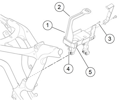
Figure 6-17. Battery tray: 1. Battery tray; 2. Battery strap support; 3. Screw (3); 4. Oil tank vent clip; 5. Battery cable clip
5. Lift up battery tray slightly so that mounting tabs will clear mounts on frame. As you lift up on tray, pull down gently on end of battery strap support (2) to clear frame and wiring harnesses above battery tray.
6. Remove negative battery cable and vent line from battery tray retaining clips.
7. Slide battery tray out and remove from left side.
Installation
| FASTENER | TORQUE VALUE | |
| Battery tray mounting fasteners | 96-156 in·lbs | 10.9-17.6 Nm |
| Stop lamp switch bracket screw | 72-120 in·lbs | 8.1-13.6 Nm |
| Brake hose clamp to battery tray screw | 30-40 in·lbs | 3.4-4.5 Nm |
| ECM caddy fastener | 72-96 in·lbs | 8.1-10.8 Nm |
1. See Figure 6-16. Make sure the TSM/TSSM/HFSM connector [30B], the antenna connector [208B] (HFSM only) and the rear stop lamp switch assembly (2) are out of the way.
2. See Figure 6-17. Slide battery tray (1) into place. Make sure battery tray mounting tabs are positioned behind (to the right of) frame mounts.
3. Secure the negative battery cable and the oil tank vent line to the battery tray retaining clips (4, 5).
4. Install three screws (3) to secure battery tray to frame. Do not tighten screws until all three have been started. Tighten to 96-156 in·lbs (10.9-17.6 Nm).
5. XL models only: see Figure 6-16. Position rear stop lamp switch as follows:
- a. Install rear stop lamp switch (2). Secure with TORX screw (3). Tighten to 72-120 in·lbs (8.1-13.6 Nm).
- b. Secure brake hose clamp (5) to battery tray with screw. Tighten to 30-40 in·lbs (3.4-4.5 Nm).
- c. Install ECM caddy fastener (1). Tighten to 72-96 in·lbs (8.1-10.8 Nm).
- d. Install rear brake master cylinder reservoir. See 2.13 REAR BRAKE MASTER CYLINDER RESERVOIR.
- e. Install reservoir cover.
6. Install TSM/TSSM/HFSM into cavity in bottom of battery tray. See 6.7 TURN SIGNAL AND SECURITY MODULE (TSM/TSSM/HFSM).
Warning! Connect positive (+) battery cable first. If positive (+) cable should contact ground with negative (-) cable connected, the resulting sparks can cause a battery explosion, which could result in death or serious injury.
7. Install battery. See 1.22 BATTERY MAINTENANCE.
8. Install left side cover. See 2.18 LEFT SIDE COVER.