Removal
Warning! To protect against shock and accidental start-up of vehicle, disconnect the negative battery cable before proceeding. Inadequate safety precautions could result in death or serious injury.
1. Remove right side cover and maxi-fuse. See 8.5 Maxi-fuse.
2. Disconnect negative battery cable.
3. Remove pillion. See 2.35 Seat.
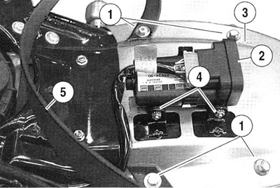
4. See Figure 2-108. Remove lock nuts (4) holding turn sig-nal/security module (TSSM) bracket. Thread lock nuts on bracket for use later. Fold module (2) and bracket aside.

Figure 2-108. Rear fender components (under pillion): 1. Fender to inner fender bolts; 2. TSSM module; 3. Fender; 4. TSSM bracket lock nuts; 5. Grabstrap
5. Remove fasteners (1) holding fender to inner fender. Remove grabstrap (5) and lift fender up from seat end.
6. Separate tail/stop lamp connector [93] and remove fender and stop light assembly.
7. Disconnect:
- Left [19] and right [18] rear turn signals.
- License plate lamp connector [45].
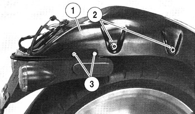
8. See Figure 2-109. Remove fasteners (3) holding rear turn signal and license plate bracket to inner fender.

Figure 2-109. Inner fender and rear turn signal and license plate bracket: 1. Inner fender; 2. Inner fender bolts; 3. Rear turn signal and license bracket bolts
9. Remove fasteners (2) holding inner fender to fender support brackets.
10. Remove fasteners mounting inner fender to fender weldment. Remove wiring harness as required and remove inner fender (1).
11. To remove two fender support brackets, use a suitable lift to support motorcycle under frame until rear tire is slightly off ground.
12. Remove upper shock bolts and capture shock mounting nuts. Lower tire to ground. See 2.32 Rear shock absorbers.
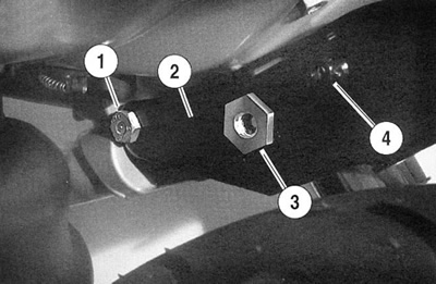
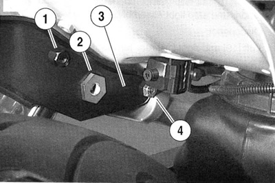
13. See Figure 2-110. Remove two inner bolts fastening support brackets to frame side rails. Remove support brackets.

Figure 2-110. Right side fender support bracket: 1. Mounting bolt; 2. Fender support bracket; 3. Upper shock mounting nut; 4. Inner fender mounting stud

Figure 2-111. Left side fender support bracket: 1. Inner fender mounting stud; 2. Lower shock mounting nut; 3. Fender support bracket; 4. Mounting bolt
14. Remove mud flap stud plate and mudflap.
15. Install rear fender and install grabstrap. Tighten to 8-12 Nm (71-106 in-lbs).
16. Install turn signal/security module (TSSM) and bracket.
17. Install pillion. See 2.35 Seat.
18. Connect negative battery cable. Tighten to 6.8-10.8 Nm (60-96 in-lbs).
19. Install maxi-fuse and right side cover.
Warning! Check for proper turn signal and tail lamp operation before riding motorcycle. Visibility is a major concern for motorcyclists. Failure to have proper lamp operation could result in death or serious injury.
20. Verify turn signal lamp operation.
Installation
1. Install mudflap and stud plate to frame fender weldment. Tighten to 8-12 Nm (70.8-106.2 in-lbs).
2. See Figure 2-110. Loosely install both fender support brackets (2). Finger tighten fasteners (1).
3. Insert upper shock mounting nut (3) through support bracket and into frame side rails.
4. Lower motorcycle on rear tire to align rear shock mounting eye with mounting nuts. Install rear shock mounting bolt and spacers. See 2.32 Rear shock absorbers.
5. Tighten fasteners:
- a. Rear shock mounting bolts - 41-68 Nm (30-50 ft-lbs).
- b. Fender support bracket fasteners - 34-41 Nm (25-30 ft-lbs).
6. Install inner fender. Tighten fasteners to 20-26 Nm (15-19 ft-lbs).
7. Route wiring harness for tail/stop lamp, license plate lamp, and turn signals. Install turn signal and license plate bracket assembly. Tighten to 8-12 Nm (71-106 in-lbs).
8. Connect:
- a. Left [19] and right [18] rear turn signals.
- b. License plate lamp connector [45].
- c. Tail/stop lamp connector [93].
