Removal
1. Block motorcycle underneath frame so front wheel is off the ground.
Warning! To protect against shock and accidental start-up of vehicle, remove the maxi-fuse before proceeding. Inadequate safety precautions could result in death or serious injury.
2. Remove right side cover and maxi-fuse.
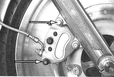
3. See Figure 2-65. Remove both upper and lower mounting bolts to remove brake caliper assembly.

Figure 2-65. Caliper mounting bolts
4. Support calipers using a rubber bungee cord. Be careful not to scratch fender or fork slider finish.
5. Repeat to remove opposite caliper.
Note. Do not operate front brake lever with the front wheel removed or the caliper piston may be forced out of piston bore. Reseating the piston requires disassembly of the caliper.
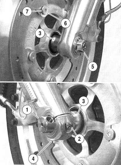
6. See Figure 2-66. Loosen pinch bolts (2) in right side axle holder (4).

Figure 2-66. Front wheel mounting: 1. Axle; 2. Pinch bolts (screws); 3. Left and right wheel spacer; 4. Axle holder (right side only); 5. Axle nut; 6. Bolt; 7. Spring washer
7. Insert screwdriver or steel rod through hole in axle (1) on right side. While holding axle stationary, remove axle nut (5).
8. Pull axle out while retaining the left and right wheel spacers (3).
9. Remove wheel assembly from forks.
Disassembly
Note. See 2.26 Tires to service tire or valve stem assembly.
1. Remove spacers from left and right sides.
2. If tire replacement is necessary, remove tire and valve stem. See 2.26 Tires.
3. If wheel bearing replacement is necessary, remove the sleeve and press out the sealed wheel bearings. See 2.24 Sealed wheel bearings.
4. If it is necessary to remove brake discs and if wheel is to be assembled with same discs, mark both wheel and discs, so they can be installed in their original locations.
5. See Figure 2-64. If removing brake discs (5), remove five bolts (2) and spring washers (3) securing brake disc to the wheel (1). Repeat procedure to remove disc on opposite side of wheel. Discard bolts and spring washers.
Cleaning and inspection
1. Thoroughly clean all parts in solvent.
2. Inspect all parts for damage or excessive wear.
Warning! Always replace brake pads in complete sets for correct brake operation. Never replace just one brake pad. Failure to install brake pads as a set could result in death or serious injury.
3. Inspect brake discs. Measure disc thickness for excessive wear. Minimum acceptable thickness is stamped on side of disc. Also replace discs if warped or badly scored. See 1.10 Brake pads and discs.
4. Inspect brake pads. Minimum brake pad thickness is 1.6 mm (0.06 in.). See 1.10 Brake pads and discs.
Assembly
Warning! Do not allow brake fluid, bearing grease, lubricants, etc. to contact brake rotor or reduced braking ability will occur which could result in death or serious injury.
Note. Always install first of two bearings on the side opposite the valve stem side of the wheel.
1. If sealed wheel bearings must be serviced, always replace bearings as a complete set. See 2.24 Sealed wheel bearings.
Warning! Do not exceed the maximum tire pressure listed on the sidewall. Incorrect tire pressure could lead to premature tire failure and possible death or serious injury.
2. If necessary, mount tire, valve stem and balance wheel assembly as required. See 2.26 Tires.
3. Verify that wheel and tire are true. See 2.26 Tires and 2.25 Disc rim runout.
Warning! Do not allow brake fluid, bearing grease, lubricants, etc. to contact brake rotor or reduced braking ability will occur which could result in death or serious injury.
4. See Figure 2-64. If necessary, install brake discs in their original positions. Verify that brake disc is clean.
- a. On left side of wheel, install five new bolts (2) and five new spring washers (3) to attach left brake disc. Tighten bolts to 21-31 Nm (16-23 ft-lbs).
- b. On right side of wheel, install five new bolts (2) and five new spring washers (3 to attach right brake disc. Tighten bolts to 21-31 Nm (16-23 ft-lbs).
5. After wheel is balanced, apply a coat of LOCTITE® ANTI-SEIZE LUBRICANT to entire surface of right side bearing race.
Installation
1. Apply a light coat of LOCTITE® ANTI-SEIZE LUBRI-CANT to the axle.
2. See Figure 2-67. Place wheel and spacers into front fork and install axle (5). Verify that axle spacers on right and left side are properly installed.

Figure 2-67. Aligning fork to wheel: 1. Fork slider; 2. Axle holder pinch bolt; 3. Axle holder; 4. Drill bit, screwdriver or steel rod; 5. Axle
3. Thread on the axle nut. Insert drill bit, screwdriver or steel rod through hole in axle on right side of vehicle. While holding axle stationary, tighten axle nut to 68-75 Nm (50-55 ft-lbs).
4. Insert 7/16" drill bit (4) into hole in axle (5).
5. Pull fork leg so that it just contacts the drill bit, screwdriver or steel rod and then tighten axle holder pinch bolts (3) to 16 Nm (12 ft-lbs). Ensure that gap between the axle holder (3) and the fork slider (1) is equal at front and rear of axle holder.
6. Remove drill bit, screwdriver or steel rod from axle hole.
Warning! Do not allow brake fluid, bearing grease, lubricants, etc. to contact brake rotor or reduced braking ability will occur which could result in death or serious injury.
7. Install the brake caliper to the fork legs.
- a. Loosely install long mounting bolt into top hole on fork leg.
- b. Install short mounting bolt into bottom hole on fork leg. Tighten bottom mounting bolt to 38-52 Nm (28-38 ft-lbs).
- c. Final tighten top mounting bolt to 38-52 Nm (28-38 ft-lbs).
8. Repeat steps 6-7 to install brake caliper on other side of wheel.
Warning! Whenever a wheel is installed, BEFORE moving motorcycle, you must pump brake fluid until the pistons push the pads against the brake disc. If you don’t pump fluid pressure up again, the brakes will not be available to stop the motorcycle which could result in death or serious injury.
9. Pump brake hand lever to move pistons out until they contact both brake pads. Verify piston location against pads.
Warning! lways test motorcycle brakes at low speed after completing repairs or bleeding the system. Failure to do so could result in death or serious injury.
10. Replace maxi-fuse and right side cover.
