General
Refer to the VRSCA Electrical Diagnostic Manual for information on the function and testing of the throttle position sensor (TP sensor).
Removal
1. Remove airbox and air filter. See 1.4 Airbox and air filter.
Caution! If airbox is not to be reinstalled immediately, cover throttle body intakes with tape to prevent contaminates/ objects from falling down the throttle bores. Do not use shop rags or objects that could damage te throttle body butterflies.
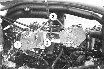
2. See Figure 9-4. Cover air intakes (3) to prevent debris from entering cylinders.

Figure 9-4. Throttle position sensor: 1. Throttle position sensor (TP sensor); 2. TP sensor connector [88B]; 3. Air intakes (covered)
Warning! To protect against shock and accidental start-up of vehicle, disconnect the negative battery cable before proceeding. Inadequate safety precautions could result in death or serious injury.
3. Disconnect negative battery cable.
4. Unplug TP sensor connector [88B] (2) by pulling external latch outward and using rocking motion to remove.
5. Remove two screws to detach TP sensor (1) from throttle body. Discard screws.
Installation
Notes:
- Throttle must be closed for proper installation of throttle position sensor.
- Throttle position sensor does not have to be adjusted.
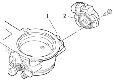
1. See Figure 9-5. With connector facing rear of vehicle, verify that shaft pocket of TP sensor fits over shaft on throttle body.

Figure 9-5. Throttle position sensor installation: 1. Shaft; 2. Shaft pocket
2. Align holes in TP sensor with holes in throttle body.
Note. TP sensor may have to be turned slightly for holes to align.
3. Install new screws and tighten to 2.0-2.8 Nm (18-25 in-lbs).
4. See Figure 9-4. Connect TP sensor connector (2).
5. Connect negative battery cable.
6. Install airbox and air filter. See 1.4 Airbox and air filter.
