Function
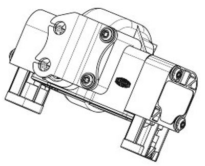
The throttle grip is the part to which the throttle control cables arrive; its task is to translate the rider's power request (Demand) into an electrical signal to be sent to the electronic control unit.
Operating principle
The two throttle cables (opening and closing) actuate on a scroll mounted on a shaft which is sent back to its home position by a return spring. On the shaft covers there are 2 double track potentiometers (4 control tracks) by means of which the torque demand is read (and checked). The 4 potentiometers are tinned and magnetically controlled (contactless); they cannot be overhauled nor replaced
Level in wiring diagram: Throttle grip position sensor.
Location:
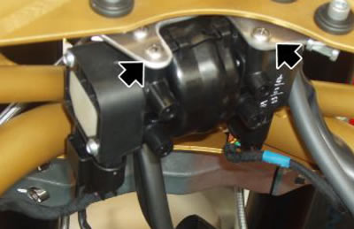
- on the vehicle: under the fuel tank
- connector: direct to the Marelli control unit

Electrical characteristics:
- Not detected by a multimeter as they are contactless: read voltage on the 4 tracks through Axone.
Caution! Before carrying out any troubleshooting, carefully read the general troubleshooting concepts for electrical devices at the beginning of the check and control section in the electrical system chapter.
Caution! The two connectors which get to the throttle grip sensor are alike but they should never be inverted. Mark or check the connector marking before removing them (blue stamp + blue band). The connector and the blue band should be placed to the left. The connector and the white band should be placed to the right.

Axone: parameters
Left side throttle grip position sensor - track A
Example value: 1107 mV
Voltage value of the left potentiometer track A
Left side throttle grip position sensor - track B
Example value: 1107 mV
Voltage value times 2 of the left potentiometer track B
Right side throttle grip position sensor - track C: 3560 mV
Voltage value of the left potentiometer track C
Right side throttle grip position sensor - track D: 3555 mV
Voltage value times 2 of the left potentiometer track D
Throttle grip position sensor: 1107 mV
Voltage corresponding to the potentiometer track A
Throttle grip opening percentage: 0%
With a released throttle grip, the value read should be 0%, whereas 100% should be read with throttle grip fully twisted.
Axone: statuses
Throttle grip
Example value: Slightly twisted_choked_fully twisted
Throttle grip autodetection
Example value: carried out/not carried out
Axone: parameter adjustment
Throttle grip autodetection
Axone: electrical errors
Left side throttle grip position sensor track A P0150 - short circuit to positive / open circuit, short circuit to negative
Error cause
If shorted to positive: excessive voltage has been detected at PIN 42 of the VEHICLE connector. If the circuit is open, shorted to negative: voltage equal to zero has been detected at PIN 42 of the VEHICLE connector.
Troubleshooting
If shorted to positive: check the value shown by the parameter of the left Throttle Grip Position Sensor - track A: disconnect the left connector and see the value displayed by Axone: if the voltage does not vary, there is a short circuit in the cable wiring; replace the throttle grip sensor if the voltage drops to zero.
If the circuit is open, short circuit to negative: check the throttle grip sensor connector and the Marelli control unit connector. If not OK, restore. If OK, check circuit continuity between the two cable terminals. If not OK, restore; if OK, check the cable earth insulation (from the throttle grip sensor connector or the control unit connector): if the cable is not earth insulated, restore the wiring. If it is earth insulated, and with the key set to ON, check that there is power supply for the potentiometer PIN A and that PIN C is connected to earth. If both are correct, replace the throttle grip sensor; if not, check the continuity of the cable that is not functioning properly: if there is continuity, replace the control unit; if not, restore the wiring
Left side Throttle Grip Position sensor - track B P0151 - short circuit to positive / open circuit, short circuit to negative
Error cause
Voltage that is excessive / equal to zero has been detected at PIN 40 of the VEHICLE connector.
Troubleshooting
short circuit to positive: check the value shown by the parameter of the left Throttle Grip position Sensor track B: disconnect the left connector and see the value displayed by Axone: if the voltage does not vary, there is a short circuit in the cable wiring; replace the throttle grip sensor if the voltage drops to zero.
If the circuit is open, short circuit to negative: check the throttle grip sensor connector and the Marelli control unit connector. If not OK, restore. If OK, check circuit continuity between the two cable terminals. If not OK, restore; if OK, check the cable earth insulation (from the throttle grip sensor connector or the control unit connector): if the cable is not earth insulated, restore the wiring. If it is earth insulated, and with the switch key set to ON, check that there is power supply for the potentiometer PIN D and that PIN F is connected to earth. If both are correct, replace the throttle grip sensor; if not, check the continuity of the cable that is not functioning properly: if there is continuity, replace the control unit; if not, restore the wiring.
Right side Throttle Grip Position sensor - track C P0152 - short circuit to positive / open circuit, short circuit to negative.
Error cause
If shorted to positive: excessive voltage has been detected at PIN 30 of the ENGINE connector. If the circuit is open, shorted to negative: voltage equal to zero has been detected at PIN 30 of the ENGINE connector.
Troubleshooting
If shorted to positive: check the value shown by the parameter of the right Throttle Grip position Sensor - track C: disconnect the right side connector and see the value displayed by the Axone: if the voltage does not vary, there is a short circuit in the cable wiring; replace the throttle grip sensor if the voltage drops to zero.
If the circuit is open, short circuit to negative: check the throttle grip sensor connector and the Marelli control unit connector. If not OK, restore. If OK, check circuit continuity between the two cable terminals. If not OK, restore; if OK, check the cable earth insulation (from the throttle grip sensor connector or the control unit connector): if the cable is not earth insulated, restore the wiring. If it is earth insulated, and with the key set to ON, check that there is power supply for the potentiometer PIN A and that PIN C is connected to earth. If both are correct, replace the throttle grip sensor; if not, check the continuity of the cable that is not functioning properly: if there is continuity, replace the control unit; if not, restore the wiring
Right side Throttle Grip Position sensor - track D P0153 - short circuit to positive / open circuit, short circuit to negative.
Error cause
If shorted to positive: excessive voltage has been detected at PIN 44 of the ENGINE connector. If the circuit is open, shorted to negative: voltage equal to zero has been detected at PIN 44 of the ENGINE connector.
Troubleshooting
if shorted to positive: check the value shown by the parameter of the right Throttle Grip Position Sensor - track D: disconnect the right side connector and see the value displayed by the Axone: if the voltage does not vary, there is a short circuit in the cable wiring; replace the throttle grip sensor if the voltage drops to zero.
if the circuit is open, short circuit to negative: check the throttle grip sensor connector and the Marelli control unit connector. If not OK, restore. If OK, check circuit continuity between the two cable terminals. If not OK, restore; if OK, check the cable earth insulation (from the throttle grip sensor connector or the control unit connector): if the cable is not earth insulated, restore the wiring. If it is earth insulated, and with the switch key set to ON, check that there is power supply for the potentiometer PIN D and that PIN F is connected to earth. If both are correct, replace the throttle grip sensor; if not, check the continuity of the cable that is not functioning properly: if there is continuity, replace the control unit; if not, restore the wiring.
Axone: logic errors
Left side Throttle Grip Position (tracks A-B) P0154 - illogical signals.
Error cause
Two illogical voltage signals have been detected at PINS 42 and 40 of the VEHICLE connector (tracks A-B)
Troubleshooting
Check the parameters of the left Throttle Grip Position Sensor - tracks A and B: if one of the two values clearly deviates from 600-1400 mV, it means that this potentiometer is defective. Check the throttle grip sensor connector and the control unit connector: if not OK, restore. If OK, check that cable resistance between the throttle grip sensor connector and the control unit is a few tenths of Ohm: if this is not the case, restore wiring. If the value is correct, replace the complete throttle grip sensor.
Right side Throttle Grip Position (tracks C-D) P0155 - illogical signal.
Error cause
Two illogical voltage signals have been detected at PINS 30 and 44 of the ENGINE connector (tracks A-B)
Troubleshooting
Check the parameters of the left Throttle Grip Position Sensor - tracks C and D: if one of the two values clearly deviates from 600-1400 mV, it means that this potentiometer is defective. Check the throttle grip sensor connector and the control unit connector: if not OK, restore. If OK, check that cable resistance between the throttle grip sensor connector and the control unit is a few tenths of Ohm: if this is not the case, restore wiring. If the value is correct, replace the complete throttle grip sensor
Throttle Grip position P0156 - illogical signal.
Error cause
The value of the left side sensor (tracks A-B) does not coincide with the value of the right side sensor (tracks C-D).
Troubleshooting
Replace the throttle grip sensor
Reset procedure
If the Marelli control unit or the throttle grip sensor is replaced, check the Throttle grip Autodetection with the diagnosis instrument: once the check is completed, make sure that the throttle grip Autodetection status indicates: carried out.
Caution! The two connectors which get to the throttle grip sensor are alike but they should never be inverted. Mark or check the connector marking before removing them (blue stamp + blue band). The connector and the blue band should be placed to the left. The connector and the white band should be placed to the right.
Note. The two connectors which get to the throttle grip sensor are the same but they should NEVER be inverted. Mark or check the connector marking before removing them (blue stamp+blue band).
Removal
When required, disconnect the corresponding connectors, undo and remove the two screws and remove the throttle grip position sensor.

