Note: Aligning the final drive pinion gear and ring gear is necessary when any of the following parts are replaced:
- Final drive housing
- Any bearing
1. Select:
- final drive pinion gear shim(-s) (1)
- ring gear shim(-s) (2)
a. Position the final drive pinion gear and the ring gear with shims (1) and (2). Calculate the respective thicknesses from information marked on the final drive housing and the drive pinion gear.
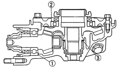
(1) Final drive pinion gear shim; (2) Ring gear shim; (3) Thrust washer
b. To find final drive pinion gear shim thickness "A" use the following formula:
- Final drive pinion gear shim thickness A = (84 + a/100) - b
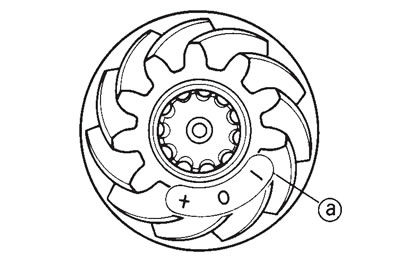 |  |
Where:
a = a numeral (positive or negative) on the ring gear, to be divided by 100 and added to "84"
b = a numeral on the final drive housing.
Example:
If the final drive pinion gear is marked "+01" and the final drive housing is marked "83.50":
A = (84 + 1/100) - (83.50) = (84 + 0.01) - (83.50) = 84.01 - 83.50 = 0.51
Therefore, the calculated final drive pinion gear shim thickness is 0.51 mm.
Shim sizes are supplied in the following thicknesses.
- Final drive pinion gear shim: Thickness (mm): 0.30, 0.40, 0.50
Since the final drive pinion gear shims are only available in 0.10 mm increments, round off to the hundredths digit.
| Hundredths | Rounded value |
| 0, 1, 2, 3, 4 | 0 |
| 5, 6, 7, 8, 9 | 10 |
In the example above, the calculated final drive pinion gear shim thickness is 0.51 mm. The chart instructs you to round off the 1 to 0. Thus, you should use a 0.50 mm final drive pinion gear shim.
c. To find ring gear shim thickness "B", use the following formula:
Ring gear shim thickness: B = b + c — [(35.40 + d/100) + f ]
 | 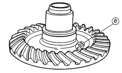 |
Where:
- (c) = a numeral on the final drive housing.
- (d) = a numeral usually on the outside of the ring gear bearing housing.
- (e) = a numeral (positive or negative) on the inside of the ring gear, to be divided by 100 and added to "35.40".
- (f) = the ring gear bearing thickness constant.
- Ring gear bearing thickness "(f)": 13.00 mm
Example:
If the final drive housing is marked "45.51" the ring gear bearing housing is marked "3.35" the ring gear is marked "-05", and "f" is 13.00:
B = 45.51 + 3.35 - [(35.40 - 5/100) + 13] = 45.51 + 3.35 - [(35.40 - 0.05) + 13] = 48.86 - [35.35 + 13] = 48.86 - 48.35 = 0.51
Therefore, the calculated ring gear shim thickness is 0.51 mm.
Shim sizes are supplied in the following thickness.
- Ring gear shim: Thickness (mm): 0.30, 0.40, 0.50
Since the ring gear shims are only available in 0.10 mm increments, round off the hundredths digit.
| Hundredths | Rounded value |
| 0, 1, 2, 3, 4 | 0 |
| 5, 6, 7, 8, 9 | 10 |
In the example above, the calculated final gear shim thickness is 0.51 mm. The chart instructs you to round off the 1 to 0. Thus, you should use a 0.50 mm ring gear shim.
2. Install:
- shim(s) (as calculated)
- final drive pinion gear
- bearing retainer: 115 Nm (11.5 m·kg) (with the bearing retainer wrench)
Caution! The bearing retainer has left-hand threads. To tighten the bearing retainer, turn it counterclockwise.

- Bearing retainer wrench: 90890-04077
3. Install:
- gear coupling
- self-locking nut: 130 Nm (13.0 m·kg) (with the special tool (1))
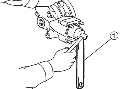
- Coupling gear/middle shaft tool: 90890-01229
Caution! Apply LOCTITE® to the self-locking nut.
4. Install: ring gear bearing housing (along with the ring gear, but without the thrust washer)
5. Adjust: ring gear backlash. Refer to "Measuring the ring gear backlash" and "Adjusting the ring gear backlash".
6. Measure: ring-gear-to-thrust-washer clearance
a. Remove the ring gear bearing housing (along with the ring gear).
b. Place four pieces of Plastigauge® between the original thrust washer and the ring gear.
c. Install the ring gear bearing housing and tighten the bolts, and nuts to specification.
- Ring gear bearing housing bolt (M10): 40 Nm (4.0 m·kg)
- Ring gear bearing housing nut (M8): 23 Nm (2.3 m·kg)
Note: Do not turn the final drive pinion gear and ring gear while measuring the ring-gear-to-thrust-washer clearance with Plastigauge®.
d. Remove the ring gear bearing housing.
e. Measure the width of the flattened Plasti-gauge® (1).
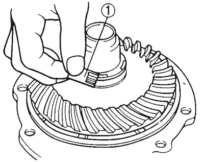
- Ring-gear-to-thrust-washer clearance: 0.2 mm
f. If the ring-gear-to-thrust-washer clearance is within specification, install the ring gear bearing housing (along with the ring gear).
g. If the ring-gear-to-thrust-washer clearance is out of specification, select the correct thrust washer as follows.
h. Select the suitable thrust washer from the following chart.
- Thrust washer: Thickness (mm): 1.2, 1.4, 1.6, 1.8, 2.0
i. Repeat the measurement steps until the ring-gear-to-thrust-washer clearance is within the specified limits.
- Ring-gear-to-thrust-washer clearance: 0.2 mm
