Valve clearance adjustment should be made on a cold engine, at room temperature.
When the valve clearance is to be measured or adjusted, the piston must be at top dead center (TDC) on the compression stroke.
1. Remove:
- Rider seat
Refer to "GENERAL CHASSIS".
- Fuel tank
Refer to "FUEL TANK".
- Air filter case
Refer to "AIR FILTER CASE".
- Lower cowlings
- Side cowlings
Refer to "GENERAL CHASSIS".
- Throttle body assembly
Refer to "THROTTLE BODIES".
- Air cut-off valve
Refer to "AIR INDUCTION SYSTEM".
- Radiator
- Radiator fan motor
Refer to "RADIATOR".
2. Remove:
- Ignition coils
- Spark plugs
- Cylinder head cover
- Cylinder head cover gasket
Refer to "CAMSHAFTS".
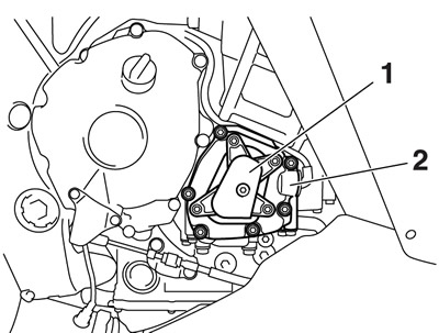
3. Remove:
- Pickup rotor cover 1 "1"
- Pickup rotor cover 2 "2"
4. Measure:
- Valve clearance
Out of specification → Adjust.
Valve clearance (cold) Intake 0.11-0.20 mm (0.0043-0.0079 in). Exhaust 0.21-0.25 mm (0.0083-0.0098 in).
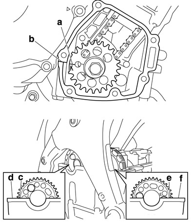
a. Turn the crankshaft clockwise and align the pickup rotor K mark "a" and crankcase occluding surface "b".
(At this time, make sure the intake camshaft sprocket punch mark "c" and cylinder head occluding surface "d", and exhaust camshaft sprocket punch mark "e" and cylinder head occluding surface "f" are aligned. If not, repeat until they are aligned.).
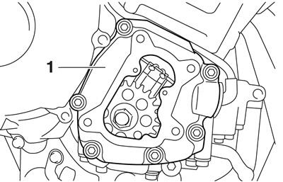
b. Install the pickup rotor cover 2 "1".
c. Turn the crankshaft 105 degrees in clockwise and align the pickup rotor K mark "a" and crankshaft position sensor I mark "b".
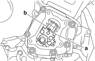
d. Measure the valve clearance #1 with a thickness gauge "1".
Thickness gauge 90890-03180. Feeler gauge set YU-26900-9.
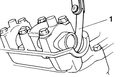
e. Turn the crankshaft 260 degrees in clockwise and align the pickup rotor I mark "a" and crankshaft position sensor I mark "b".
f. Measure the valve clearance #3 with a thickness gauge.
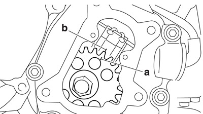
Thickness gauge 90890-03180. Feeler gauge set YU-26900-9.
g. Turn the crankshaft 205 degrees in clockwise and align the pickup rotor T mark "a" and crankshaft position sensor I mark "b".
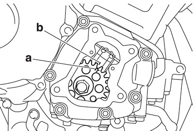
h. Measure the valve clearance #2 and #4 with a thickness gauge.
Thickness gauge 90890-03180. Feeler gauge set YU-26900-9.
If the valve clearance is incorrect, record the measured reading.
Measure the valve clearance in the following sequence.
Valve clearance measuring sequence.
Cylinder #1 → #3 → #2 → #4
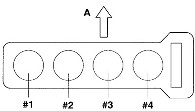
A. Front
5. Remove:
- Camshafts
Refer to "Camshafts".
When removing the timing chain and camshafts, fasten the timing chain with a wire to retrieve it if it falls into the crankcase.
6. Adjust:
- Valve clearance
a. Remove the valve lifter "1" and the valve pad "2" with a valve lapper "3".
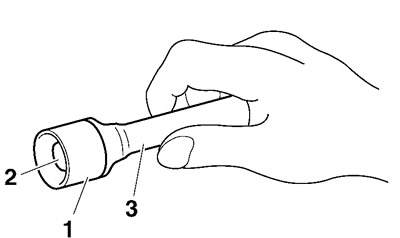
Valve lapper 90890-04101. Valve lapping tool YM-A8998.
Cover the timing chain opening with a rag to prevent the valve pad from falling into the crankcase.
Make a note of the position of each valve lifter "1" and valve pad "2" so that they can be installed in the correct place.
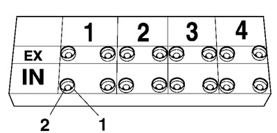
b. Select the proper valve pad from the following table.
| Valve pad range | Nos. 120-240 |
| Valve pad thickness | 1.20-2.40 mm (0.0472-0.0945 in) |
| Available valve pads | 38 thicknesses in 0.05 mm (0.002 in) increments |
The thickness "a" of each valve pad is marked in hundredths of millimeters on the side that touches the valve lifter.
Since valve pads of various sizes are originally installed, the valve pad number must be rounded in order to reach the closest equivalent to the original.
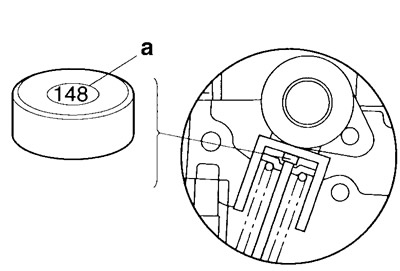
c. Round off the original valve pad number according to the following table.
| Last digit | Rounded value |
| 0 or 2 | 0 |
| 5 | 5 |
| 8 | 10 |
Example:
- Original valve pad number = 148 (thickness = 1.48 mm (0.058 in))
- Rounded value = 150.
d. Locate the rounded number of the original valve pad and the measured valve clearance in the valve pad selection table. The point where the column and row intersect is the new valve pad number.
The new valve pad number is only an approximation. The valve clearance must be measured again and the above steps should be repeated if the measurement is still incorrect.
e. Install the new valve pad "1" and the valve lifter "2".
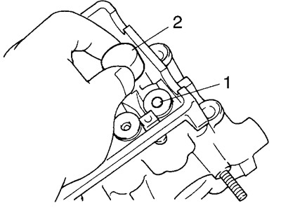
Lubricate the valve pad with molybdenum disulfide oil.
Lubricate the valve lifter with engine oil.
The valve lifter must turn smoothly when rotated by hand.
Install the valve lifter and the valve pad in the correct place.
f. Install the exhaust and intake camshafts, timing chain and camshaft caps.
Camshaft cap bolt 10 Nm (1.0 m·kgf, 7.2 ft·lbf).
Refer to "Camshafts".
Lubricate the camshaft lobes and camshaft journals.
First, install the exhaust camshaft.
Align the camshaft marks with the camshaft cap marks.
Turn the crankshaft counterclockwise several full turns to seat the parts.
g. Measure the valve clearance again.
h. If the valve clearance is still out of specification, repeat all of the valve clearance adjustment steps until the specified clearance is obtained.
7. Install:
- All removed parts
For installation, reverse the removal procedure.
