
To check and adjust the thermal clearances of the valves, it is necessary to remove the cylinder head cover (see «Cylinder head - removal and installation»).
Attention! Checking the thermal clearances of the valves is carried out on a cold engine (temperature not higher than 30°C).
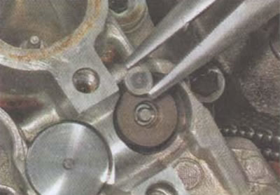
The value of thermal gaps is checked with flat probes.
I. With a 10 mm hex wrench, unscrew the plug of the right crankcase cover.
Attention! It is allowed to rotate the crankshaft only in the direction of engine operation (clockwise).
2. Using a 14 mm socket wrench, rotate the crankshaft by the generator rotor bolt until the drive cam of the valve being measured is in position «closed». Gap A is measured between the pusher and the cam in a position where the cam does not interact with the pusher (valve closed).
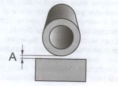
3. We measure the gap. The gap is equal to the probe rating if the probe moves between the shaft cam and the pusher with some effort (dipstick «fails» - the gap is larger, it enters with excessive force - the gap is less than the nominal value of the probe).

The nominal clearance for the intake valves is 0.15±0.03 mm.
The nominal clearance for exhaust valves is 0.22±0.03 mm.
4. Write down the clearance values for each valve.
5. If the gaps are within the allowable values, the work can be considered completed. If the gap of any valve is outside the specified values, it must be adjusted. The Honda CB400SF motorcycle uses a valve clearance adjustment scheme using shims of various thicknesses. The change in the thermal clearance of the valve occurs due to the gradual wear of all parts of the valve mechanism. Adjusting washers of different thicknesses compensate for excessively large or small clearance, changing the overall height of the valve-pusher block.
Attention! When removing the pushers, it is important not to mix them up. It is most convenient to lay them out on a clean cloth or paper in the order in which they were installed in the engine and sign.
6. Remove the camshafts and remove the pushers from the sockets of the cylinder head (see «Cylinder head - removal and installation»).
7. Remove the shims.

Attention! As a rule, the washers are removed together with the pushers, sticking to them on a layer of oil, but it also happens that the adjusting washer remains in the valve spring seat. In this case, remove the washer with a magnet or tweezers.
Attention! When calculating the thickness of a new washer, do not take into account the thickness indicated on the surface of the old washer. The fact is that during operation the thickness of the washer decreases and becomes less than the value indicated in the marking.
8. Using a micrometer, measure the actual thickness of the washer.
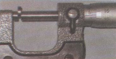
We calculate the thickness of the new washer using the formula A = B + (C - 0.15) - for intake valves, A = B + (C - 0.22) - for exhaust valves, where A is the thickness of the required washer, B is the thickness of the old washer, C is the measured clearance.
Example
If the measured clearance on the intake valve is 0.20 mm and the thickness of the installed washer is 1.850 mm, then the thickness of the new washer should be 1.90 mm: 1.85 + (0,20 - 0,15) = 1.90. We select the washer closest in thickness, that is, 1,900 mm. As a result, the thermal gap in the valve will be 0.15 mm.
The manufacturer produces 65 sizes of washers with a thickness from 1.200 mm to 2.800 mm in increments of 0.025 mm - 1.200-1.225-1.250-1.275-1.300, etc.
The thickness of the washer is applied on one of its sides by electrographic method.
9. Install a new washer in the seat of the valve disc.

10. Install the pusher.
11. Repeat steps 7-9 for all other valves.
12. We install the camshafts, camshaft bearing caps and tighten the bolts of their fastening with the specified force (see «Cylinder head - removal and installation»).
13. Using a 14 mm socket wrench, turn the engine crankshaft 3-4 turns, again check by marks whether the timing phases are correctly set, and once again control the thermal clearances of the valve mechanism.
14. We further assemble the engine in the reverse order (see «Cylinder head - removal and installation»).