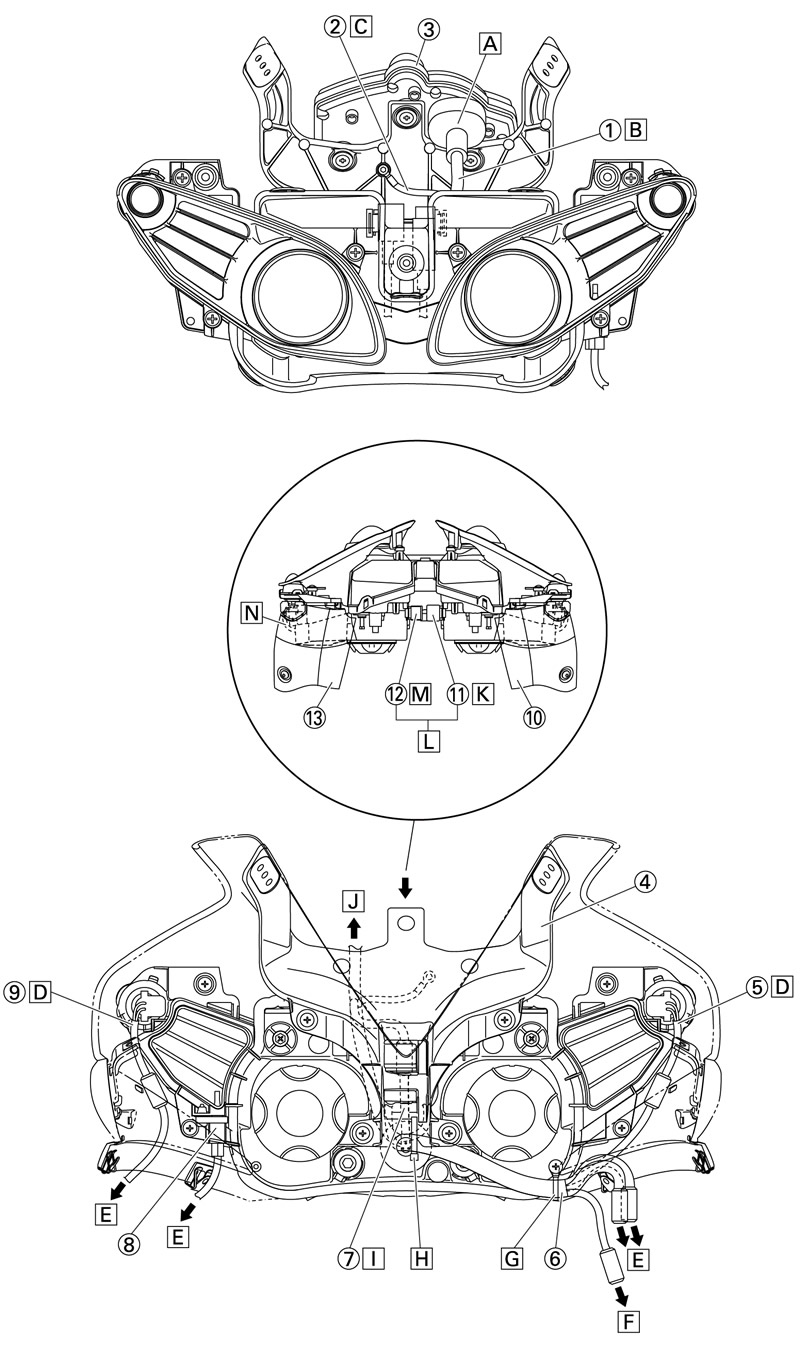
1. Meter lead; 2. Ground lead; 3. Meter; 4. Meter bracket; 5. Right auxiliary light lead; 6. Headlight sub-wire harness; 7. Headlight lead; 8. Intake air temperature sensor; 9. Left auxiliary light lead; 10. Right air intake air duct cover; 11. Turn signal relay; 12. Headlight relay; 13. Left air intake air duct cover; A. Make sure to insert the coupler and boots into the meter. Edge of the boots should not turn inward/outward; B. The meter lead should not protrude out; C. The ground lead should not protrude out. The ground lead terminal can be in any side; D. Route the auxiliary light lead under the front intake air duct and connect; E. To the main harness; F. To the turn signal; G. Cut off the excess end of the clamp; H. When clamping the headlight sub-wire harness, it should not be sagged. Face the end of the clamp to front; I. Route the headlight lead toward the front of the meter bracket and connect; J. To the meter; K. Fix the turn signal relay by inserting it all the way in to the headlight right rib; L. The turn signal relay and headlight relay can be installed either right/left; M. Secure the headlight relay by inserting it all the way in to the headlight left rib; N. The auxiliary light lead should not be pinched when installing the air intake air duct cover. Fit it inside of the console panel.
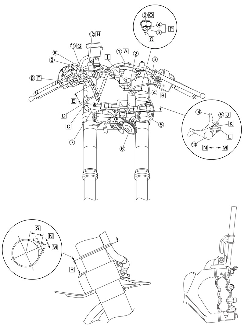
1. Clutch cable; 2. Main switch lead; 3. Left handlebar switch lead; 4. Steering damper lead; 5. Horn lead; 6. Horn; 7. Brake hose; 8. Front brake light switch lead; 9. Throttle cable (decelerator cable); 10. Throttle cable (accelerator cable); 11. Right handlebar switch lead; 12. Throttle cable; 13. Steering damper bracket; 14.Lower bracket; A. After passing the clutch cable through the clutch cable guide, route it along and front of the main switch; B. Route the clutch switch lead outside of the left handlebar switch lead; C. Fasten the brake hose with the outer tube of the front fork; D. The clamp should be above the front brake hose. The throttle cable (decelerator cable) should be on the bottom and the throttle cable (accelerator cable) should be above. Fit the clamp toward outside rather than inside; E. 30-60 mm (1.18-2.36 in); F. Route the front brake light switch lead under the brake hose. G. Route the right handlebar switch lead above the metal fitting on the brake hose; H. Route the throttle cable above the under bracket, inside of the front fork and under the brake fluid reservoir hose; I. Fasten the plastic band inside of the front fork. Fasten the band at position of the main switch lead (white), left handlebar switch lead (blue) and steering damper lead (white); J. Clamp the horn lead back and inside of the lower bracket projection; K. Lower bracket projection; L. Face the end of the plastic band to the left and cut off the excess end leaving 2-4 mm (0.08-0.16 in); M. Outside of the vehicle; N. Inside of the vehicle; O. The main switch lead should be to the back of the vehicle; P. Front of the vehicle (The left handlebar switch lead and steering damper lead can switch sides.); Q. Face the end of the plastic band to front and cut off the excess end leaving 2-4 mm (0.08-0.16 in); R. 20-40 mm (0.79-1.57 in)
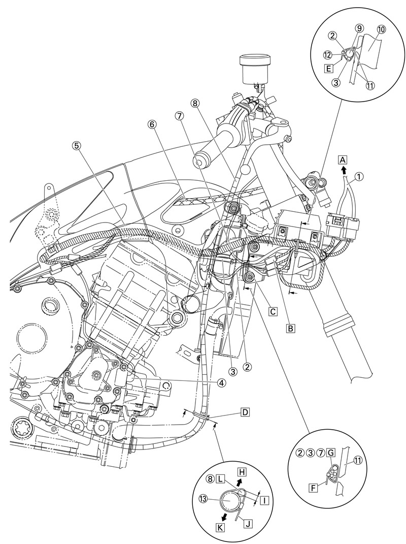
1. Headlight sub-wire harness; 2. Right radiator fan motor lead; 3. AC magneto lead; 4. Crankshaft position sensor; 5. Coolant reservoir hose; 6. Throttle cable; 7. Right handlebar switch lead; 8. Clutch cable; 9. Main harness; 10. Rectifier/regulator; 11. Rectifier/regulator bracket; 12. Right handlebar switch lead; 13. Oil cooler outlet hose; A. To the headlight; B. Make sure the right radiator fan motor lead coupler and two right handlebar switch lead couplers do not overlap in the horizontal direction; C. Out of the two slits at the root of the recti-fier/regulator bracket rib, clamp at the back of the slit; D. Clamp the clutch cable and oil cooler outlet hose at the protector rivet ring of the clutch cable; E. Clamp the right radiator fan motor lead, right handlebar switch lead, main harness and AC magneto lead under the rectifier/ regulator bracket rib and face the end of the clamp down; F. Clamp the right radiator fan motor lead, right handlebar switch lead and AC magneto lead under the rectifier/regulator bracket rib and face the end of the clamp down; G. Order insignificant-right radiator fan motor lead, right handlebar switch lead, AC magneto lead; H. Outside of the vehicle; I. Outermost part of the clutch cable should be outward than outermost part of the oil cooler outlet hose; J. Face the end of the clamp to inside; K. Inside of the vehicle; L. Clamp the clutch cable in front of the oil cooler outlet hose.
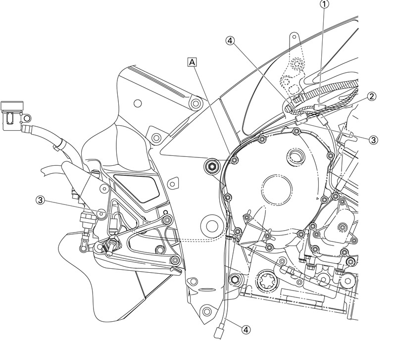
1. Ignition coil lead; 2. Crankshaft position sensor lead; 3. Rear brake light switch lead; 4. O2 sensor lead; A. Route the rear brake light switch lead outside of the O2 sensor lead and push it to the occluding surface of the clutch cover.
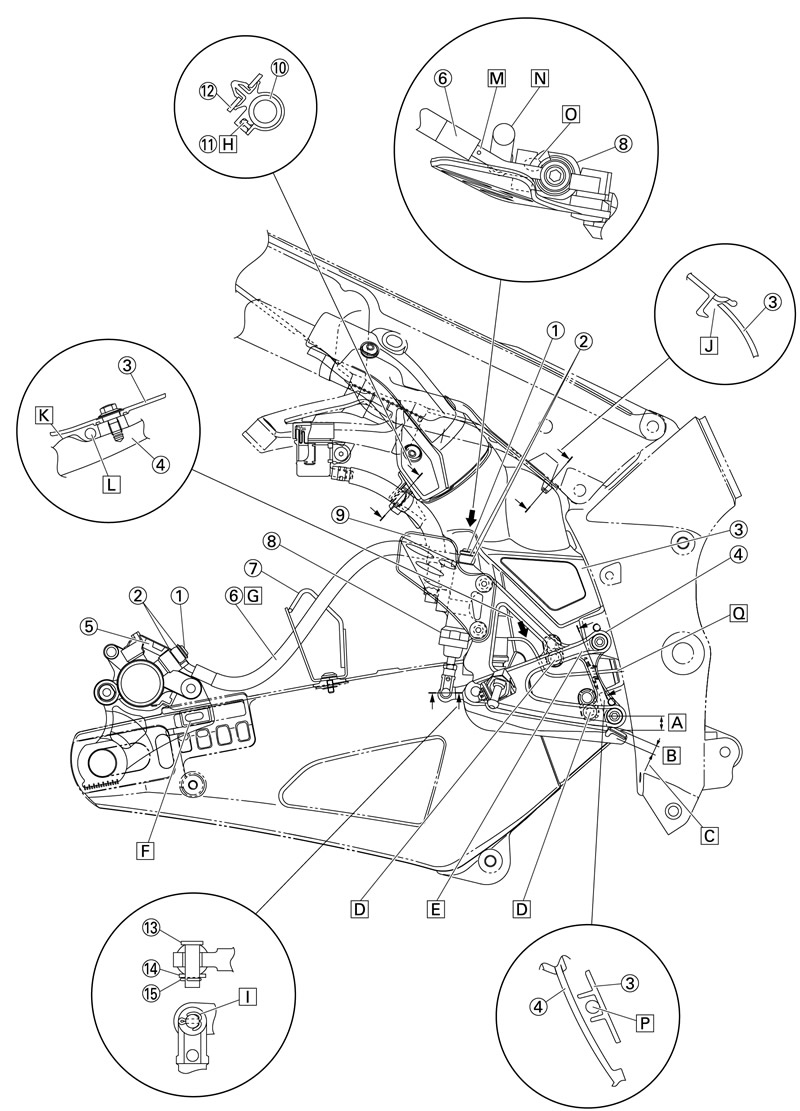
1. Union bolt; 2. Washer; 3. Exhaust chamber cover; 4. Right footrest assembly; 5. Brake caliper; 6. Brake hose; 7. Brake hose holder; 8. Brake master cylinder; 9. Footrest plate; 10. Brake fluid reservoir hose; 11. Clamp; 12. Right muffler pipe cover; 13. Pin; 14. Washer; 15. Cotter pin; A. 12-18 mm (0.47-0.71 in); B. 6-12 mm (0.24-0.47 in); C. Fit the lightening point of the brake light within 6-12 mm (0.24-0.47 in) by adjusting the adjusting nut of the rear brake light switch; D. Install the exhaust chamber cover to the right footrest assembly by aligning it to the bottom hole of the exhaust chamber cover; E. Adjust the sag of the rear brake light switch lead so that it is not outside of the right footrest assembly; F. When installing the rear brake caliper bracket, make sure to fit the torque receptor convex of the rear brake caliper bracket and torque receptor groove of the swingarm. G. Make sure to pass the brake hose through the brake hose holder. H. Face the clamp in the direction shown in the illustration. I. Make sure to bend the cotter pin. It can be bent in the same direction. J. Positioning of the exhaust chamber cover and exhaust chamber upper cover is shown in the illustration. K. Projection of the right footrest assembly; L. When installing the exhaust chamber cover, route the rear brake light switch lead in front of the projection of the right footrest assembly. M. Install the brake hose with its paint mark facing the brake master cylinder and upward. N. Route the brake fluid reservoir hose inside of the brake hose. O. Install the brake hose by contacting it against the stopper. P. Route the rear brake light switch lead between the ribs of the exhaust chamber cover. Q. Route the rear brake light switch lead between the top and bottom frame bosses for installing the right footrest assembly and to inside of the frame.
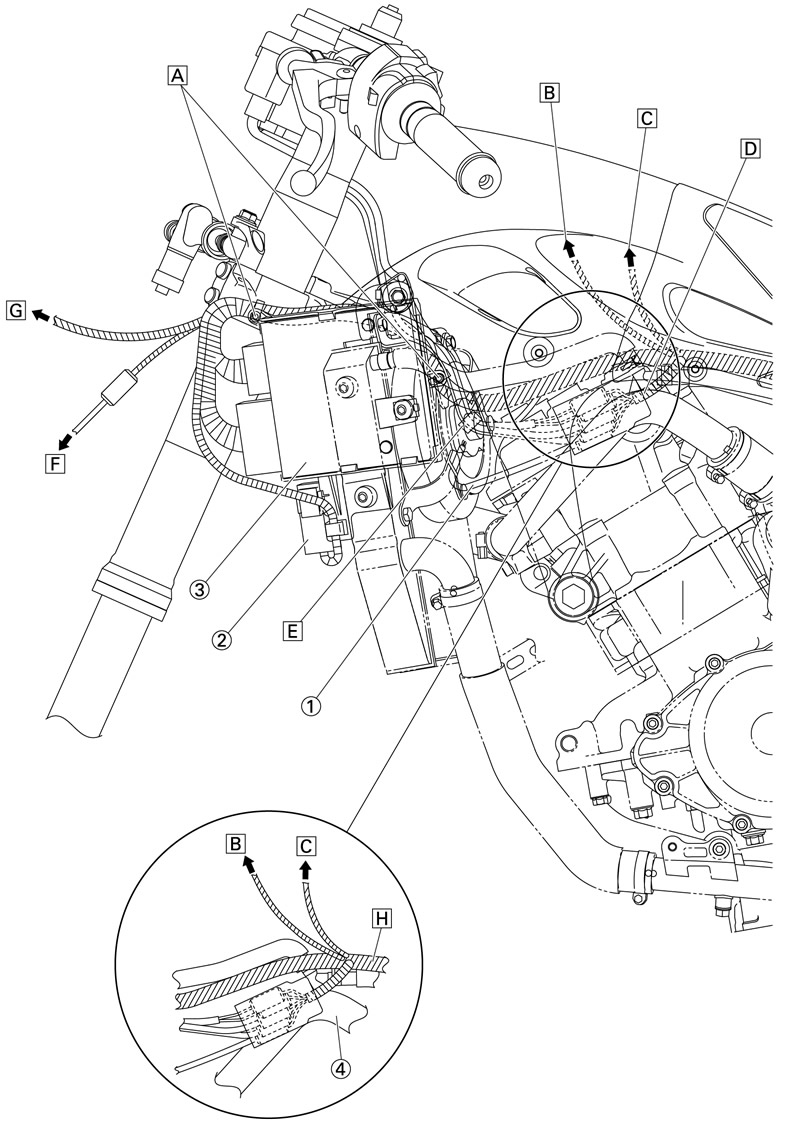
1. Left radiator fan motor lead; 2. Radiator fan motor relay; 3. ECU (engine control unit); 4. Radiator inlet pipe; A. Insert the clamp winding the main harness into the ECU bracket hole. B. To the main harness branch lead, throttle body; C. To the throttle position sensor (for throttle valves); D. Connect the left handlebar switch lead, main switch lead, steering damper lead and left radiator fan motor lead and put the connector cover. E. Clamp the left handlebar switch lead, main switch lead and steering damper lead under the main harness. Ratchet of the clamp can face in any direction. F. To the turn signal; G. To the intake air temperature sensor, headlight; H. Route the main harness outside of the radiator inlet pipe.
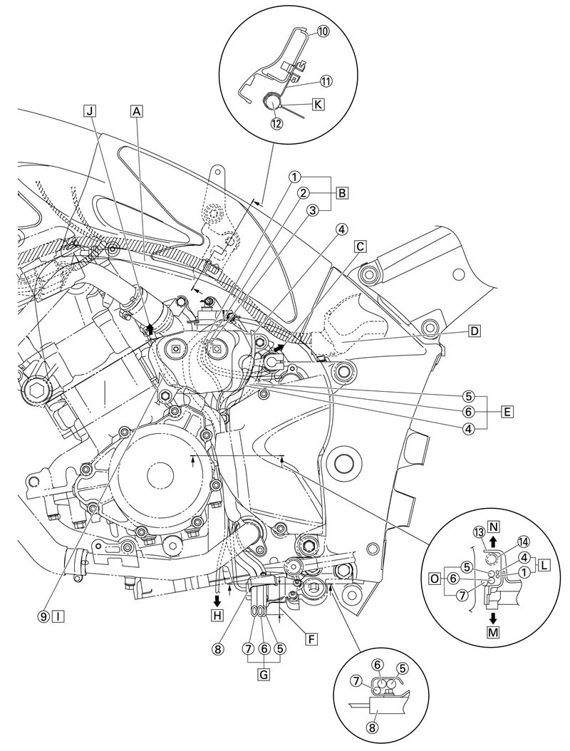
1. Oil level switch lead; 2. Gear position sensor lead; 3. Speed sensor lead; 4. Sidestand switch lead; 5. Fuel tank breather hose (Except for California); 6. Fuel tank overflow hose; 7. Coolant reservoir breather hose; 8. Sidestand switch; 9. AC magneto lead; 10. Frame; 11. Main harness holder; 12. Main harness; 13. Drive sprocket cover; 14. Water pump bypass hose; A. Route the thermostat bypass hose 2 under the main harness. B. Route the oil level switch lead, gear position sensor lead and speed sensor lead through inner side of the coolant reservoir tank and to main harness. C. To the fuel tank; D. Refer to fuel tank section. E. Push the fuel tank breather hose, fuel tank overflow hose and sidestand switch lead inside of the flange of the drive sprocket cover. F. 30-50 mm (1.18-1.97 in); G. Route the fuel tank breather hose, fuel tank overflow hose and coolant reservoir breather hose inner side of the water pump bypass hose, then through the binding clamp on the sidestand switch and to the outside of the under cover. End of the hoses can face in any direction. H. To the oil level switch; I. Route the AC magneto lead through inner side of the coolant reservoir tank and front and under the thermostat housing and to right side of the vehicle. J. To the rectifier/regulator; K. Clamp the main harness and route it through the hole on the side of the main harness holder. Align it to the main harness tape (purple). Do not cut the end and face it inside of the vehicle (same for right & left). L. Order insignificant-oil level switch lead, sidestand switch lead; M. Inside of the vehicle. N. Outside of the vehicle. O. Order insignificant-fuel tank breather hose, fuel tank drain hose and coolant reservoir drain hose.
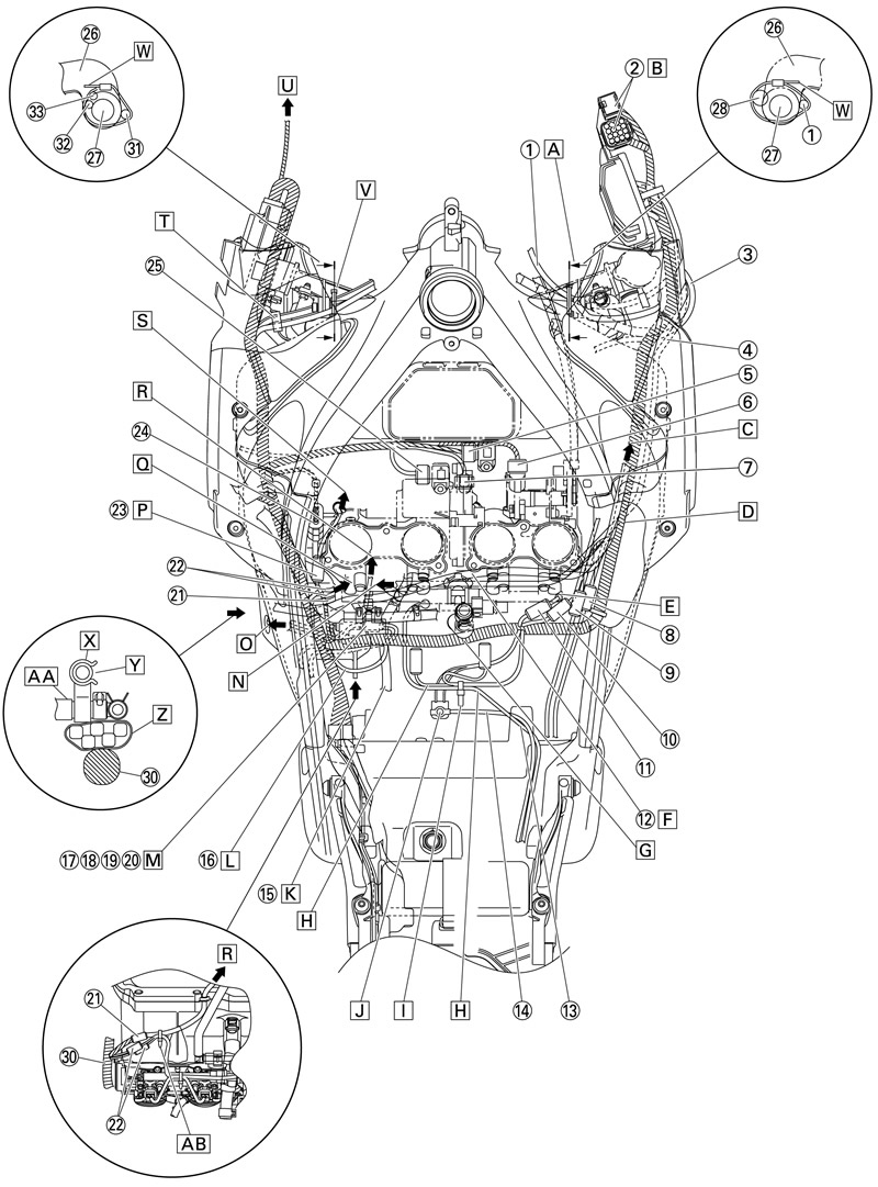
1. Right handlebar switch lead; 2. Headlight sub-wire harness; 3. Right radiator fan motor lead; 4. AC magneto lead; 5. Atmospheric pressure sensor; 6. Throttle position sensor (for throttle cable pulley); 7. Throttle servo motor; 8. O2 sensor lead; 9. Rear brake light switch lead; 10.Ignition coil lead; 11.Crankshaft position sensor lead; 12.Coolant reservoir hose; 13.Starter motor lead; 14.Battery negative lead; 15.Canister purge hose (California only) 16.Sidestand switch; 17.Oil level switch lead; 18.Gear position sensor lead; 19.Speed sensor lead; 20.Sidestand switch lead; 21.Secondary injector sub-wire harness; 22.Throttle sub-wire harness; 23.Intake funnel servo motor lead; 24.Throttle position sensor (for throttle valves); 25. Intake air pressure sensor; 26. Radiator stay; 27. Frame boss; 28. Clutch cable; 29. Stay 1; 30.Main harness; 31.Main switch lead; 32.Steering damper lead; 33.Left handlebar switch lead; A. Clamp the clutch cable and right handlebar switch lead to inside of the radiator stay with the clamp aligning to their white tape marks. B. After connecting the main harness and headlight sub-wire harness, insert them into the rectifier/regulator bracket stay. C. To the radiator; D. Route the coolant reservoir hose, main harness and AC magneto lead in this order from the top. Each of them can either be right or left. E. Route the ignition coil lead through the heat protector hole and to right of the engine. F. Route the coolant reservoir hose in front of the crankcase breather hose and to the coolant reservoir tank. Route it as shown in the illustration and it should not touch the air bleed hose clip. G. Route the main harness behind the crankcase breather hose. H. Route the starter motor lead and fuel pump lead under the fuel tank breather hose and fuel tank overflow hose, behind the fuel hose and above the ground lead and battery negative lead. I. Clamp at position of the starter motor lead (white) and fuel pump branch lead (purple). Do not cut the end and face the clamp to the back. J. Install with the ground lead at the bottom and the battery negative lead on the top. Install the rivet of the each lead facing up. Angle of installing each lead is shown in the illustration. K. Route the canister purge hose under the wire harness and air bleeding hose and above the coolant reservoir hose. L. Route the sidestand switch lead outside of the installation dotted line at the back of the coolant reservoir tank. M. Connect the oil level switch lead, gear position sensor lead, speed sensor lead and sidestand switch lead (order insignificant) and put the connector cover on. N. To the AC magneto; O. To the coolant reservoir tank; P. The intake funnel servo motor lead can either be on top or bottom of the branched secondary injector sub-wire harness and throttle sub-wire harness. Q. To the throttle body; R. To the air filter case; S. To the intake funnel servo motor; T. Clamp the main switch lead, left handlebar switch lead and steering damper lead between the radiator stay and main harness. Ratchet of the clamp can face in any direction. U. To the intake air temperature sensor and headlight; V. Clamp the main switch lead, left handlebar switch lead and steering damper lead to inside of the radiator stay with the clamp aligning to their white and blue tape marks. W. End of the clamp should be at front and facing down. X. Clamp the coolant reservoir hose and water pump bypass hose. Y. Install the coolant reservoir hose with the clamp opening facing up. Z. Fit the connector cover including the oil level switch lead, gear position sensor lead, speed sensor lead and sidestand switch lead (order insignificant) between the thermostat bypass hose 2 and main harness. AA. Install the water pump bypass hose with its clamp opening facing right of the vehicle. AB. Clamp the secondary injector sub-wire harness and throttle sub-wire harness at the protector. Face the end of the clamp downward.
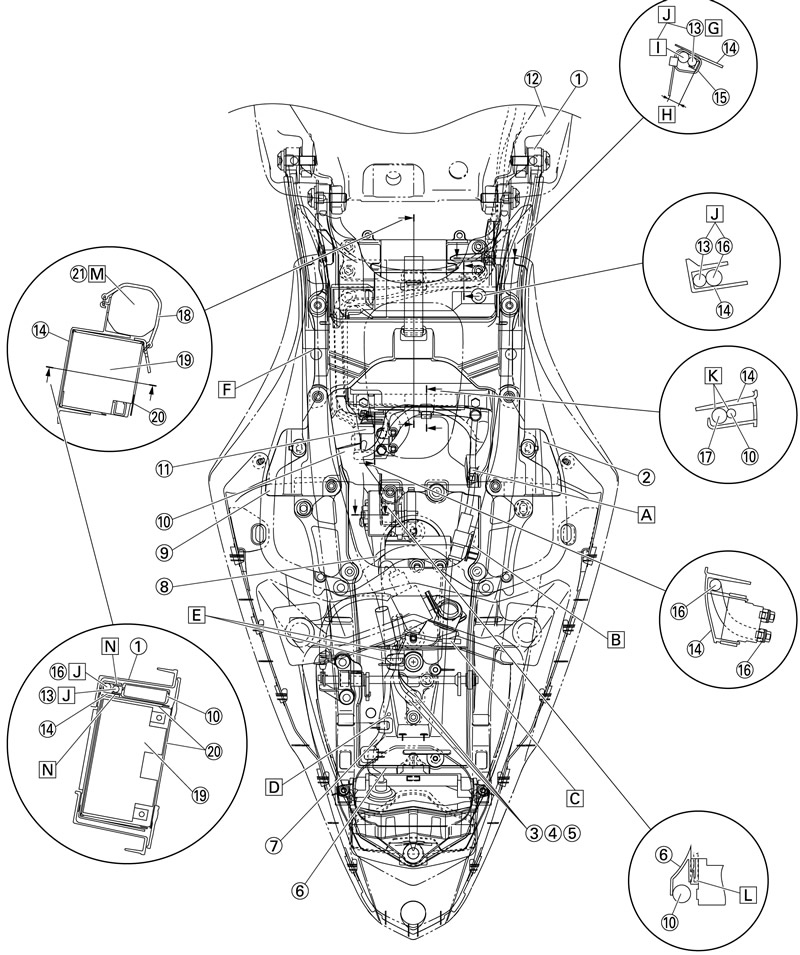
1. Rear frame; 2. Right upper tail cover bracket; 3. License plate light lead; 4. Right turn signal light lead; 5. Left turn signal light lead; 6. Battery box 2; 7. Tail/brake light lead; 8. Lean angle sensor lead; 9. Left upper tail cover bracket; 10. Main harness; 11. Starter relay; 12. Front frame; 13. Battery negative lead; 14. Battery box 1; 15. Clamp; 16. Starter motor lead; 17. Battery positive lead; 18. Tool band; 19. Battery; 20. Battery seat; 21. Tool; A. Pass the main fuse lead through the guide of the battery box 1. B. Insert the main fuse until it is completely over the tab projection of the battery box 2. C. Put the anti-theft alarm lead coupler in front of the dividing rib of the battery box 2. D. Route the tail/brake light lead through the left of the battery box 2 boss. E. After passing the tail/brake light lead, license plate light lead, right turn signal light lead and left turn signal light lead through the guide of the battery box 2, route them between the ribs. F. When installing the seal, align it to the push pin trace mark of the rear frame (both left & right). G. Align the positioning tape of the battery negative lead to the clamp. H. Face the excess end of the clamp to inside and the end should not be above the tool reception bearing surface of the battery box 1. I. Align the positioning tape of the starter motor lead to the clamp. J. Up/down position of the battery negative lead and starter motor lead is shown in the illustration. K. Install the battery positive lead (red) on top. L. Insert the fuse box until back of the tab of the battery box 2. M. Installing direction of the tool is insignificant. N. Install the main harness with its tab fitted inside of the battery box 1.
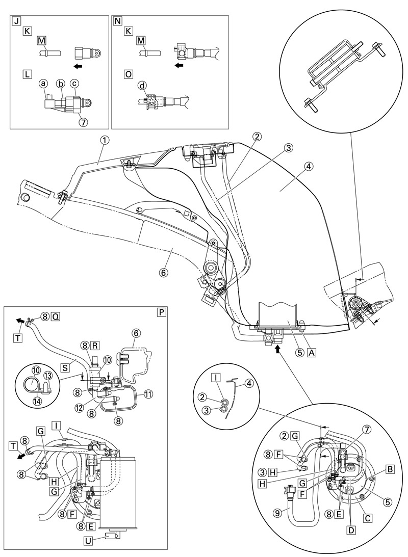
1. Fuel tank upper cover; 2. Fuel tank breather hose; 3. Fuel tank overflow hose; 4. Fuel tank; 5. Fuel pump; 6. Frame; 7. Fuel hose connector cover; 8. Clip; 9. Fuel hose; 10. Rollover valve; 11. Canister; 12. Rollover valve hose; 13. Canister bracket; 14. Clamp; A. Install the lip on the fuel pump gasket upward. B. Pump positioning punch mark; C. Install the fuel pump with the pump positioning punch mark and fuel pump bracket concave part at the same position. D. Install the fuel tank overflow hose and fuel tank breather hose with the white paint mark on each hose facing right of the vehicle. E. Align the clip knob to the paint mark on each hose and face it to right of the vehicle. F. Align the clip knob to the paint mark on each hose and face it to front of the vehicle. G. Install the fuel tank breather hose with its white paint facing front of the vehicle. H. Install the fuel tank overflow hose with its yellow paint facing front of the vehicle. I. Install the fuel tank overflow hose and fuel tank breather hose with the clamp opening facing down. J. Fuel pump side; K. Insert the connector until the click sound is heard and check that the connector does not come off. Make sure that no foreign matter is caught in the sealing section. (It is prohibited to wear the cotton work gloves or equivalent coverings.); L. After item "K" mentioned above is finished, check that the clamp is inserted from the down side "a", "b" and "c" sections are perfectly equipped. M. This part works as a dropout stopper; N. Engine side; O. After Step "K" as above is finished, check that the connector is completely attached by sliding the double lock (orange part) "d" on the connector as shown in the illustration and seeing if it touches firmly or not. P. California only; Q. Face the clip's knob upward. R. Align the clip knob to the paint mark on each hose and face it to left of the vehicle. S. Install the canister hose with the 90° bent hose to the canister side and about parallel to the rollover valve. T. To the throttle body
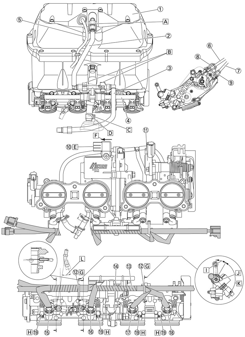
1. Upper air filter case; 2. Fuel hose (secondary injector fuel rail side); 3. Fuel hose (primary injector fuel rail side); 4. Primary injector fuel rail; 5. Sub-wire harness (secondary injector side); 6. Throttle cable (pull side); 7. Throttle cable (return side); 8. Black coating; 9. White coating; 10. Intake air pressure sensor; 11. Accelerator position sensor; 12. Plastic locking tie; 13. Sub-wire harness (primary injector side); 14. Fuel damper; 15. Injector #1 coupler; 16. Injector #2 coupler; 17. Injector #3 coupler; 18. Injector #4 coupler; 19. Cap; A. Checker color: orange; B. Checker color: black; C. Rotate the clip to the right of the vehicle. D. Adjust top edge of the clip to top edge of the paint. E. Make sure the intake air pressure sensor is touching against the stopper and install it horizontally. F. After installing the intake air pressure sensor, do not press it to the direction of the arrow. G. Position the plastic locking tie as shown in the illustration. H. It is a cap for synchronization. I. 30°; J. Mass of plastic locking ties; K. Mass of plastic locking ties should be within this range. L. 30°
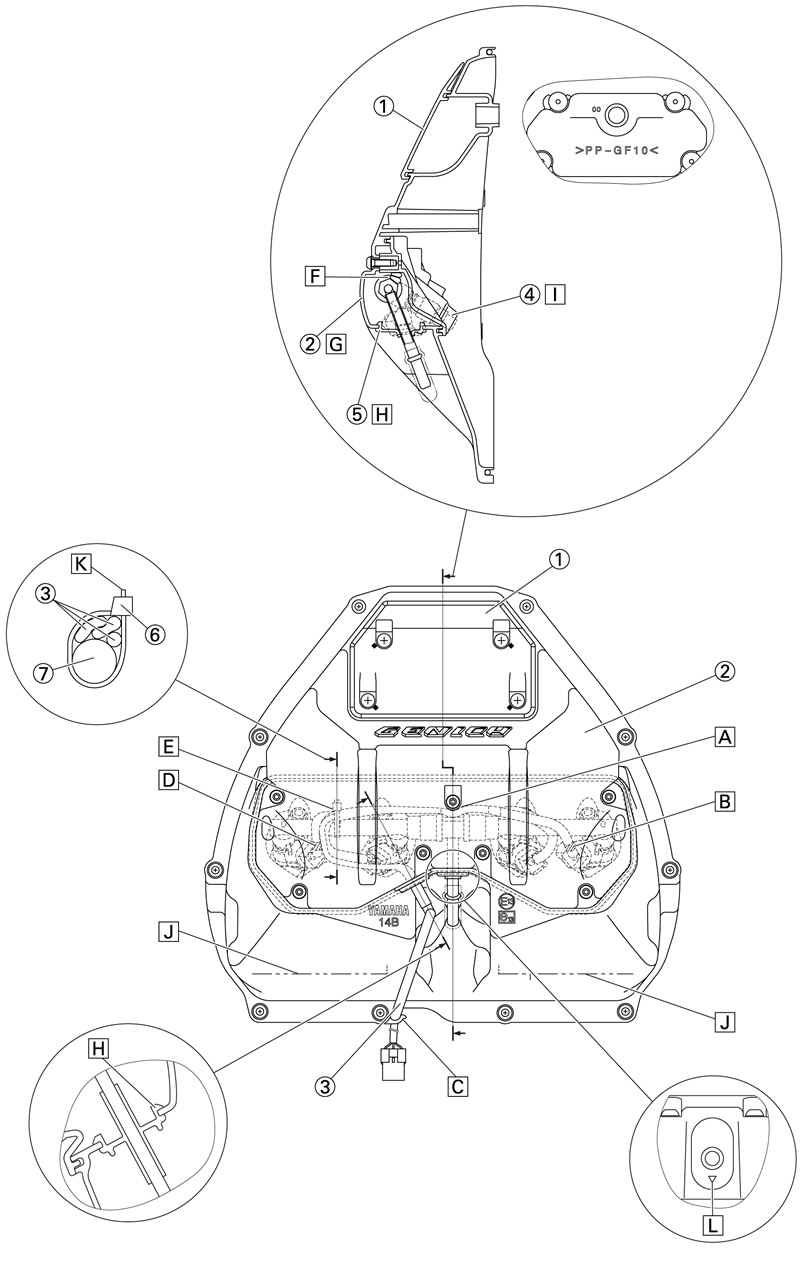
1. Cap case; 2. Upper air filter case; 3. Sub-wire harness; 4. Cap case assembly; 5. Grommet; 6. Plastic locking tie; 7. Fuel rail; A. Sub-wire harness should not be pinched under the bearing surface of the bolt. B. #4 purple tape; C. Pinch the sub-wire harness with the hook. When pinching, make sure not to change the shape of the hook. D. #1 white tape; E. Fasten the plastic locking tie at the branch root of the sub-wire harness. Position the plastic locking tie as shown in the illustration. F. Position the sub-wire harness under the bearing surface of the bolt so that it is not pinched. G. When installing the air filter case, the subwire harness should not be pinched. H. Make sure the grommet is not pinched. I. When installing the cap case assembly, the sub-wire harness should not be pinched. J. The indicated line is used as a mark for pasting the caution label for the US. K. Face the end of the plastic locking tie to front of the vehicle and cut off the excess end leaving 2-4 mm (0.08-0.16 in). L. Install with the △ mark facing down.
