Torque wrench settings:
- Shock absorber to frame (1): 50 Nm (5.0 kg·m)
- Linkages to frame (2): 50 Nm (5.0 kg·m)
- Footpeg bracket screws (3): 22 Nm (2.2 Kgm)
- Upper screws (5): 22 Nm (2.2 Kgm)
Note. Each procedure is cross-referred to the relevant section of the manual and some of the operations described there may not be necessary for the job at hand. To avoid redundant work, always make sure you really need to remove a particular component before proceeding.
Remove the engine from the frame; see 6.2.3.
Remove the instrument panel subframe; see 7.4.2.
Remove the front end complete with front wheel assembly; see 7.9.2.
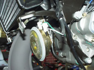
Disconnect the two horn connectors.
Working from the right-hand side, undo and remove the top nut (1).
Remove the bolt from the opposite end and collect the washer.
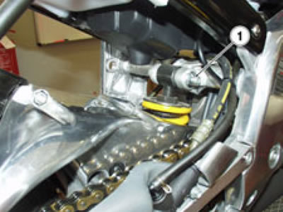
Working from the right-hand side, undo and remove the nut (2).
Remove the bolt from the opposite end and collect the washer.
Remove the rear swinging arm together with the shock absorber; see 7.11.1.
Remove the side stand; see 7.4.9.
Remove the right-hand rider footpeg bracket; see 7.4.4.

Release and remove the two screws (3).
Remove the left-hand rider footpeg bracket.

Disconnect the connector of the starter relay.
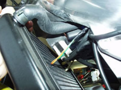
Disconnect the connector of the left light dip switch.

Disconnect the two connectors of the right light dip switch.
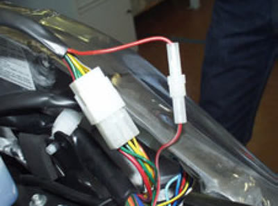
Disconnect the two connectors of the right light dip switch.

Remove the seat subframe complete with carburetor, oil tank and airbox, see 7.4.10.
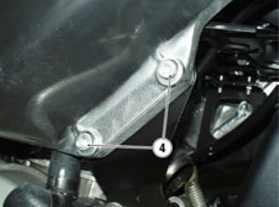
Working on both sides of the motorcycle, release and remove the two screws (4) at the front end.
Remove the two radiator brackets mounted to the battery frame.
Working on both sides of the motorcycle, release and remove the two upper screws (5).
Remove the frame head plate.

