See Figure 6-3. The electrical system relay/fuse block is located in front of the battery under the left side cover. The relays and fuses are mounted in the relay/fuse block. All fuses are rated at 15 amperes.
Main fuse
Removal
1. Open left side cover. See 2.18 LEFT SIDE COVER.
Note. Models with Sirens: Verify that fob is present and turn ignition key to IGNITION before removing main fuse or disconnecting battery.
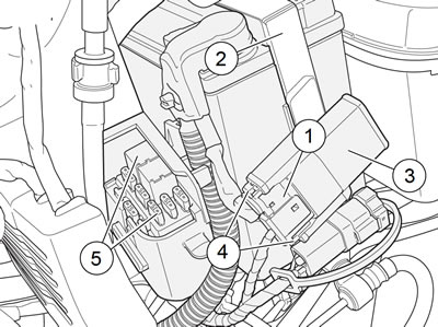
2. See Figure 6-1. Squeeze cover release latches (4) together and pull fuse holder [5] (1) from protective cover (3).

Figure 6-1. 30 A Main fuse location: all models: 1. Main fuse holder [5]; 2. Battery strap; 3. Protective cover; 4. Cover release catches; 5. Relay and fuse blocks
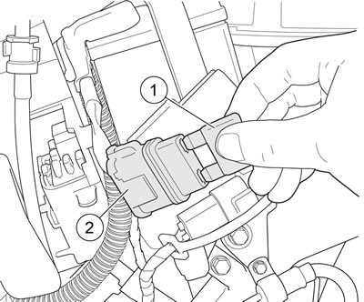
3. See Figure 6-2. Grasp fuse holder (2) and pull main fuse (1) straight out.

Figure 6-2. Removing/installing main fuse: 1. Main fuse; 2. Fuse holder [5]
4. Close left side cover.
Note. Always close left side cover if performing other procedures. Failure to close cover will cause cosmetic damage.
Installation
1. Open left side cover. See 2.18 LEFT SIDE COVER.
2. Verify ignition key is turned to OFF position.
3. See Figure 6-1. Install main fuse (1) by lining up spade terminals on fuse with sockets in fuse holder [5] (2). Press fuse firmly into holder.
4. See Figure 6-2. While holding protective cover (3) in place, push fuse holder [5] (1) into cover until cover release latches (4) snap into place.
5. Close left side cover.
Warning! Be sure that all lights and switches operate properly before operating motorcycle. Low visibility of rider can result in death or serious injury.
6. Turn ignition switch ON. Verify proper operation of electrical system.
Fuses
1. Open left side cover. See 2.18 LEFT SIDE COVER.
2. See Figure 6-3. Remove suspect fuse (3-7).
- a. Inspect fuse for damage. Always discard damaged fuses.
- b. Replace fuse by pressing firmly into socket.

Figure 6-3. Relay/fuse block (typical): 1. System relay; 2. Starter relay; 3. Ignition fuse; 4. Lights fuse; 5. Accessory fuse; 6. ECM fuse; 7. Battery fuse; 8. Spare fuse
3. Close left side cover.
4. Turn ignition switch ON. Verify operation of electrical system.
Relays
1. Open left side cover. See 2.18 LEFT SIDE COVER.
Notice: Always use replacement fuses that are of the correct type and amperage rating. Use of incorrect fuses can result in damage to electrical systems.
2. See Figure 6-3. To unplug old relay (1 or 2), grasp body of relay and with a gentle rocking motion, pull straight out from relay/fuse block.
3. To install new relay, line up spade terminals of relay with sockets in relay/fuse block and push relay firmly into sockets.
4. Close left side cover.
5. Verify operation of lighting system.
