
Wire harness connectors
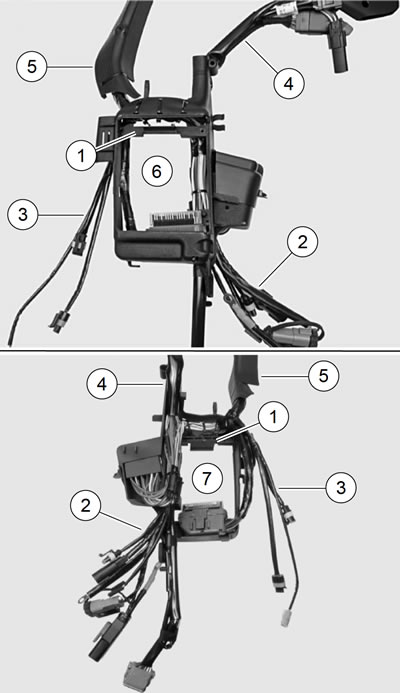
Figure 6-104. Main wiring harness: XL models: 1. ECM caddy; 2. Lower left bundle; 3. Lower right bundle; 4. Upper rear bundle; 5. Upper front bundle; 6. Front view; 7. Rear view
See Figure 6-104, Figure 6-105 or Figure 6-106. The main wiring harness can be divided up into four bundles, originating at the ECM caddy (XL models) or H-bracket (XR 1200X) (1). These bundles are:
- Lower left bundle (2) including:
- Rear stop lamp switch wires [121B],
- Crankcase ground [GND1],
- Fuel pump connector [141A],
- Siren connector [142B],
- TSM/TSSM/HFSM connector [30B],
- Main fuse holder [5],
- Data link connector [91A],
- Rear oxygen (O2) sensor connector [137B].
- Lower right bundle (3) including:
- Vehicle speed sensor (VSS) connector [65B],
- Green starter motor wire [128B],
- Engine Temperature (ET) sensor connector [90B].
- Upper rear bundle (4) including:
- ECM connector [78B],
- Engine sub-harness connector [145A],
- P&A battery connector [160B],
- Rear lighting sub-harness connector [7A],
- Fuel sender resistor assembly/connector [200].
- Upper front bundle (5) including:
- Hand control connectors [22B], [24B],
- Headlamp connector [38A],
- Front turn signal connector [31A],
- Instruments connector [20B],
- Horn wires [122B],
- Ignition switch [33],
- Coil connector [83B],
- Neutral switch connector [136B],
- Oil pressure switch connector [120B],
- Crank position (CKP) sensor connector [79B],
- Front oxygen (O2) sensor connector [138B],
- Voltage regulator DC output connector [77B].
Removal
Warning! To prevent spray of fuel, purge system of high-pressure fuel before supply line is disconnected. Gasoline is extremely flammable and highly explosive, which could result in death or serious injury.
1. Purge the fuel supply hose of high pressure gasoline. Disconnect fuel supply hose from fuel pump module. See 4.4 FUEL TANK: XL MODELS or 4.5 FUEL TANK: XR 1200X.
Warning! Prevent accidental vehicle start-up, which could cause death or serious injury. First disconnect negative (-) battery cable at engine and then positive (+) cable from battery.
3. Remove battery. See 1.22 BATTERY MAINTENANCE.
4. Remove fuel tank. See 4.4 FUEL TANK: XL MODELS or 4.5 FUEL TANK: XR 1200X.
5. XR 1200X: Remove air cleaner. See 1.7 AIR FILTER, XR 1200X.
6. Remove wire harness caddy. See 6.28 ELECTRICAL CADDIES.
7. See Figure 6-107. Cut cable strap (2) securing ET sensor to harness.

Figure 6-107. ET sensor harness: XL models: 1. Harness loop; 2. Barbed cable strap; 3. Engine temperature sensor connector location
8. Unplug the following harness connectors from the main harness:
- a. Oil pressure switch [120B],
- b. Voltage regulator DC output [77B],
- c. Crank Position (CKP) sensor [79B],
- d. Front oxygen (O2) sensor [138B],
- e. Rear oxygen (O2) sensor [137B],
- f. Neutral switch jumper [136B],
- g. Engine temperature (ET) sensor [90B],
- h. Ignition coil [83B],
- i. Horn [122B],
- j. JIffy stand sensor [133] (if equipped),
- k. ECM [78B],
- l. Harness ground wire at engine crankcase [GND1],
- m. Rear stop lamp switch [121B],
- n. Vehicle speed sensor (VSS) [65B],
- o. Green starter motor wire [128B].
- p. Optional Security Siren: Unplug security siren connector [142B].
9. Locate engine sub-harness connector [145A] and rear lighting sub-harness connector [7A] on top of oil tank. Unplug both sub-harnesses from main harness.
10. Pull P&A battery harness/connector [160B] and fuel sender resistor assembly/connector [200] out from recess in top left rear corner of oil tank, under frame.
11. Remove TSM/TSSM/HFSM. See 6.7 TURN SIGNAL AND SECURITY MODULE (TSM/TSSM/HFSM).
- a. Reach under battery tray. Push TSM/TSSM/HFSM up from cavity in bottom of tray.
- b. Unplug harness connector [30B].
- c. H-DSSS equipped models: unplug antenna connector [208B].
12. Remove wiring harness from two frame clips on front left frame downtube.
13. Remove vapor valve hose from clip on wiring harness. See 4.20 EVAPORATIVE EMISSIONS CONTROL.
14. Remove battery tray. See 6.9 BATTERY TRAY.
Note. XL Models: Remove both fasteners securing the ECM caddy.
15. See Figure 6-108. Remove the ECM caddy.

Figure 6-108. ECM caddy fasteners: 1. Lower; 2. Upper
16. Pull harness away from rear frame downtube.
17. Remove main wiring harness from left side. Carefully slide wire harness caddies between rear cylinder and frame.
Installation
| FASTENER | TORQUE VALUE | |
| ECM caddy fastener | 72-96 in·lbs | 8.1-10.8 Nm |
1. See Figure 6-104, Figure 6-105 or Figure 6-106. Loosely position new main wiring harness on vehicle. From left side, slide ECM caddy (XL models) or H-bracket (XR 1200X) (1) into position on rear frame downtube. Guide each wire bundle toward its respective area on the vehicle during installation. Verify lower right bundle (3) feeds out toward right side of vehicle.

Figure 6-105. Main wiring harness, front: XR 1200X: 1. H-bracket; 2. Lower left bundle; 3. Lower right bundle; 4. Upper rear bundle; 5. Upper front bundle
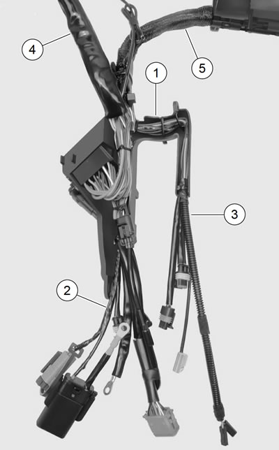
Figure 6-106. Main wiring harness, rear: XR 1200X: 1. H-bracket; 2. Lower left bundle; 3. Lower right bundle; 4. Upper rear bundle; 5. Upper front bundle
2. XL Models: Verify upper front bundle (5) with wire harness caddies feed out toward right side of vehicle. Install ECM caddy. Verify hook on ECM caddy engages tab on oil tank bracket. Tighten ECM caddy fasteners to 72-96 in·lbs (8.1-10.8 Nm). See 6.6 ELECTRONIC CONTROL MODULE (ECM).
3. XR 1200X: Press H-bracket onto rear frame downtube until it snaps in place.
4. Feed upper rear bundle (4) up over top of oil tank. Verify engine sub-harness also feeds up into that area.
5. Feed upper front bundle along frame backbone toward front of vehicle.
6. Feed TSM/TSSM/HFSM harness connector into position under battery tray location.
Note. The TSM/TSSM/HFSM harness connector MUST be in position before installing battery tray. Verify the harness feeds over the top of the oil tank return hose.
7. Install battery tray. Verify battery tray interlocks with ECM caddy (XL models) or H-bracket (XR 1200X) on left side. Re-attach rear brake hose fasteners and rear brake master cylinder reservoir. See 6.9 BATTERY TRAY.
8. Plug connector [30B] into TSM/TSSM/HFSM. H-DSSS equipped models: plug in antenna connector [208B].
9. Lower TSM/TSSM/HFSM into place in bottom of battery tray.
10. Snap vapor valve into clip on left side of ECM caddy (XL models) or H-bracket (XR 1200X). See 4.20 EVAPORATIVE EMISSIONS CONTROL.
11. Slide P&A battery harness and connector [160B] and fuel sender resistor assembly/connector [200] into recess in top left rear corner of oil tank, under frame.
12. Plug rear lighting connector [7B] into main harness connector [7A].
13. Plug engine sub-harness connector [145B] into main harness connector [145A].
14. Slide left wire harness caddy between front cylinder head and frame, from right side of vehicle toward left side.
Note. Group the neutral switch connector [136B], CKP sensor connector [79B], oil pressure switch connector [120B], front O2 sensor connector [138B] and voltage regulator DC output connector [77B] into the upper right bundle.
15. Run the upper right bundle down the front left frame downtube.
16. Install wire harness caddy. See 6.28 ELECTRICAL CADDIES.
17. Plug in the following harness connectors:
- a. Oil pressure switch [120B],
- b. Voltage regulator DC output [77B],
- c. Crank Position (CKP) sensor [79B],
- d. Front oxygen (O2) sensor [138B],
- e. Rear oxygen (O2) sensor [137B],
- f. Neutral switch jumper [136B],
- g. Engine temperature (ET) sensor [90B],
- h. Fuel pump [141A],
- i. Ignition coil [83B],
- j. Horn [122B],
- k. ECM [78B],
- l. Harness ground wire at engine crankcase [GND1],
- m. Rear stop lamp switch [121B],
- n. Vehicle speed sensor (VSS) [65B],
- o. Green starter motor wire [128B],
- p. Optional Security Siren: Plug in security siren connector [142B],
- q. Jiffy stand sensor (JSS) [133], if equipped.
18. XL Models: Secure clutch cable and wiring harness running down left frame downtube with two frame clips. Capture front O2 sensor harness with lower frame clip. Position frame clip close to bottom of upper voltage regulator bracket.
19. XR 1200X: Secure wiring harness running down left frame downtube onto both oil cooler bracket clips.
20. Secure ET sensor harness to oil tank mounting bracket with a barbed cable strap. Verify there is a loop in the harness between the ET sensor and the rear cylinder head to avoid damaging harness during vehicle operation.
Note. See Figure 6-109. Verify fuel pump harness rests in harness clip (5) on wire harness caddy latch clip (2).
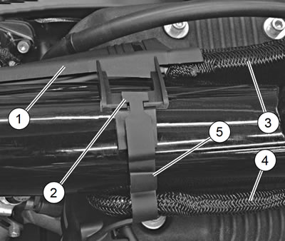
Figure 6-109. Right wire harness caddy latch clip (typical): 1. Right wire harness caddy; 2. Wire harness caddy latch clip; 3. Main harness; 4. Engine sub-harness; 5. Fuel pump harness clip
21. Install fuel tank. See 4.4 FUEL TANK: XL MODELS or 4.5 FUEL TANK: XR 1200X.
Warning! Connect positive (+) battery cable first. If positive (+) cable should contact ground with negative (-) cable connected, the resulting sparks can cause a battery explosion, which could result in death or serious injury.
22. Install battery. See 1.22 BATTERY MAINTENANCE.
23. Install left side cover. See 2.18 LEFT SIDE COVER.
Warning! After installing seat, pull upward on seat to be sure it is locked in position. While riding, a loose seat can shift causing loss of control, which could result in death or serious injury.
24. Install seat. See 2.39 SEAT.
Warning! Be sure that all lights and switches operate properly before operating motorcycle. Low visibility of rider can result in death or serious injury.
25. Verify the operation of the electrical system.