
It is not necessary to remove the power unit from the motorcycle to remove the cylinder head. (In the photographs the engine has been removed for clarity.)
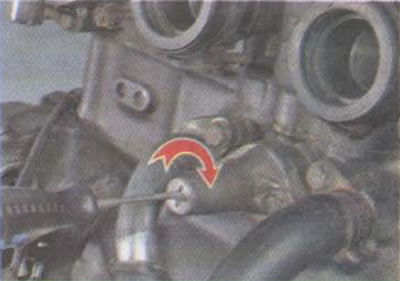
To remove the cylinder head, you must first remove the fuel tank (see «Fuel tank - removal and installation»), ignition coils (see «Ignition coils - removal and installation»), thermostat with cooling pipes (see «Thermostat - removal and installation»), exhaust system (see «System of release of the fulfilled gases - removal and installation») and carburetor bar (see «Plank carburetors - removal and installation»). You also need to drain the coolant (see «Coolant - replacement») and disconnect from the fittings the hoses of the cooling system and the tube of the crankcase ventilation system (see «Power unit - removal and installation»).
Attention! Install the cylinder head only on a new gasket. It is not allowed to reuse the old gasket, as it is crimped during installation (deformed), taking the form of a block and a head. When reinstalling, it is impossible to achieve an exact match between the positions of the block, head and gasket.
Removing
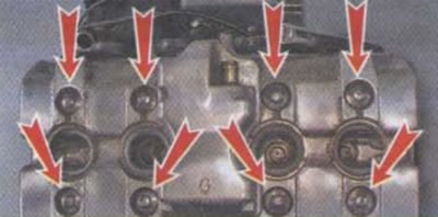
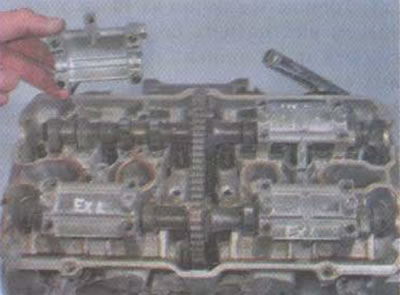
1. Using a 10 mm socket wrench, unscrew the eight bolts of the cylinder head cover.
Attention! The cover should be removed carefully so as not to damage its rubber gasket. The head cover gasket is reusable and can be installed many times.
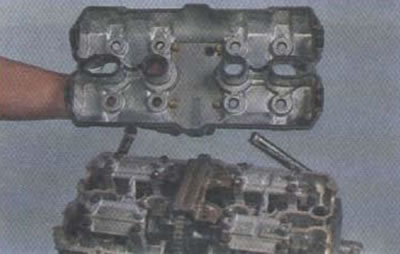
2. Remove the cover with the gasket.
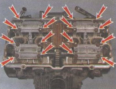
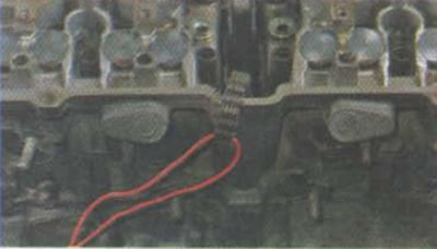
3. Using a 10 mm socket wrench, unscrew the sixteen bolts securing the camshaft bearing caps.
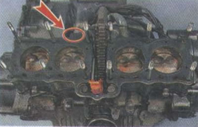
4. Remove the chain guide.
Advice. The shaft bearing caps are marked to prevent them from being mixed up during installation; however, for ease of operation, you can apply your own marks to the caps with a clerical touch, as shown in the photo.
5. Remove the shaft bearing caps.
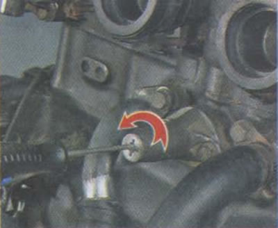
6. Using a 10 mm socket wrench, unscrew the timing chain tensioner plug.

7. Turning the tensioner screw with a thin slotted screwdriver clockwise, we compress the tensioner, thereby loosening the chain tension.
Attention! The chain tensioner is released automatically. However, if after full compression, when the screwdriver has reached the stop and does not rotate, apply a small force in the same direction, then the tensioner will remain in the folded position. If the tensioner does not lock in the folded position, it is recommended to remove it by unscrewing the two fastening bolts with an 8 mm socket wrench.
8. Remove one of the camshafts.
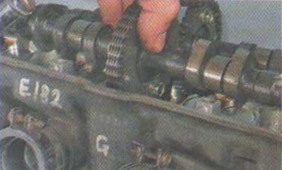
9. Remove the timing chain from the sprocket and remove the shaft.
10. Repeat steps 8-9 for the second shaft.
11. To prevent the timing chain from falling inside the engine, tie it with a piece of wire or cord.
12. We examine the shafts. The cams and bearing journals must be free of corrosion, scratches, scuffs, other mechanical damage or aluminum enveloping. There should also be no noticeable development.
- Nominal jaw height: 32.180-32.420 mm.
- The maximum height of the cams: 32.130 mm.
- Nominal bearing journal diameter: 22.959-32.420 mm.
- Maximum diameter of bearing necks: 22.950 mm.
In the presence of the indicated damage or if the indicated parameters are less than critical values, the camshaft must be replaced.
Attention!
- When installing, it is important to install each pusher exactly on the valve from which it was removed. To do this, when removing, it is best to lay out the pushers on clean paper or cloth in exactly the sequence in which they were removed.
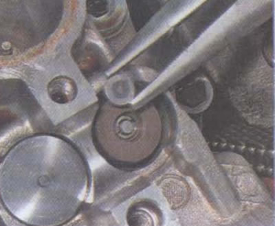
- When removing the pushers, it is important not to damage their mirrors. Therefore, when working with pliers, one must be extremely careful. You can also use a magnet to remove the pushers.
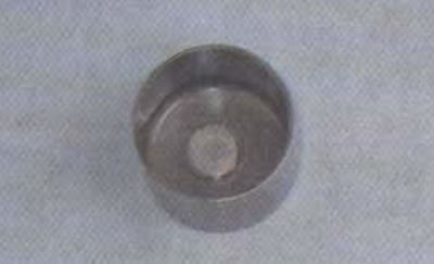
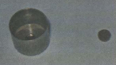
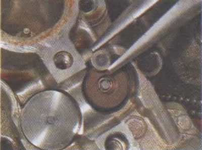
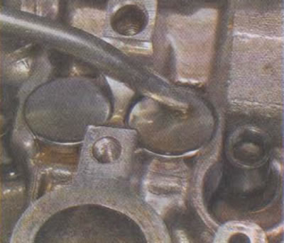
13. Using pliers with narrow jaws, we remove the valve pushers from the sockets.

14. Most often, the valve thermal clearance adjusting washers stick to the bottom of the pusher on a layer of oil and are removed along with them.
However, it is important to ensure that none of the washers remain in the valve retainer seat. If necessary, remove the washers with tweezers.
15. Using an 8 mm hex wrench, unscrew the twelve nuts securing the cylinder head.
16. Using a 10 mm socket wrench, unscrew the two central bolts of the cylinder head.
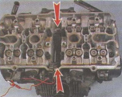
17. Remove the head from the cylinder block.
18. Remove the head gasket.
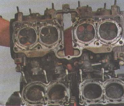
19. We clean the remnants of the gasket from the landing planes of the head and block (You can use a carburetor cleaner for this).
20. We examine the internal parts of the head.
Black soot on all valves of one cylinder indicates the re-enrichment of the mixture in this cylinder. If the carbon deposits on the exhaust valves have a brownish or reddish tint, the composition of the mixture in the cylinder is optimal. Whitish soot or its almost complete absence indicates a lean mixture in the cylinder.
21. We soak carbon deposits on valves, combustion chambers and pistons with kerosene or carburetor cleaner and clean them from carbon deposits with a metal brush.
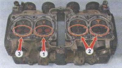
1 - the optimal composition of the mixture in the cylinder; 2 - highly enriched mixture; 3 - slightly over-enriched mixture
Installation
I. Before installing the head, it is recommended to blow out all channels (inlet, exhaust, cooling system jackets) compressed air. Particles of dirt, old gaskets, soot can damage the cylinder-piston group and other internal units. It is also necessary to blow compressed air through the channels of the jacket of the cylinder block cooling system, the cylinders themselves and the timing chain well.
2. Install a new gasket. On the side of the gasket that should be facing up (to the head), marked UP.
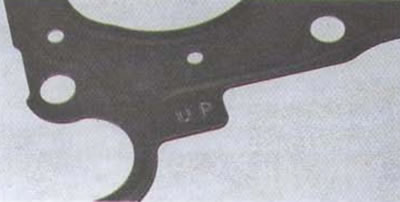
3. When installing the gasket, the UP mark must be located at the rear, in the direction of the motorcycle.
4. Reinstall the head.
5. We wrap nuts and bolts of fastening of a head against the stop, without tightening them.
6. Tighten the head bolts with a force of 12 Nm.
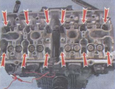
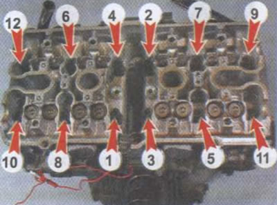
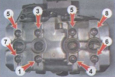
7. In several stages, we tighten the head mounting nuts in the sequence indicated by the numbers in the photo. We tighten the nuts with a force of 29 Nm.
Attention!
- Before installing the pushers, it is recommended to blow out their sockets in the head with compressed air, and also make sure that there are no dirt particles on the pusher surface. If necessary, wipe it with a cloth.
- If the pusher was washed after removal, it is necessary to lubricate the pusher mirror with engine oil before installation.
8. We remove the adjusting washer from the pusher of the corresponding valve.
9. We install it in the socket of the thrust plate of the valve spring.
10. Install the pusher in place.

I. Lubricate the plane of the pushers with engine oil.
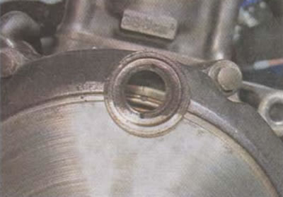
12. We turn out the plugs of the right crankcase cover. Rotating the crankshaft by the generator bolt with a 14 mm socket wrench clockwise, align the mark «T» on the flywheel with a notch on the viewing window of the engine cover.
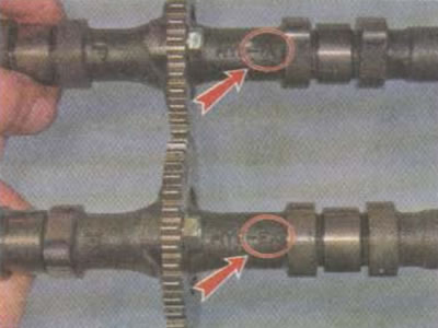
Attention! The camshafts are marked. On the intake - IN, on the exhaust - EX. When installing the shafts, it is important not to mix them up.
13. Lubricate the beds of the camshafts with engine oil.

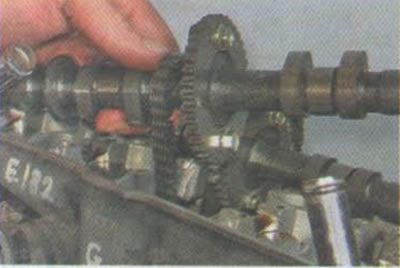
14. Install the camshafts. The marks on the camshaft sprockets must be located in the same plane with each other and with the plane of the block head.
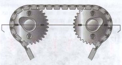
In this case, the camshaft cams should face upward and outward. By setting the shafts in this position, we set the compression stroke for the first cylinder (the first cylinder is on the left in the direction of travel of the motorcycle).

15. Lubricate the camshaft bearing journals with engine oil.

16. Reinstall the camshaft bearing caps. It is important not to mix up the lids. To do this, use the marks applied to them during disassembly, or the factory marks cast on the top surface of each cover.

Each cap has two marks. It is necessary to navigate by marks that are not painted over with paint.
- EXR - exhaust shaft, right.
- EXL - exhaust shaft, left.
- INR - intake shaft, right.
- INL - intake shaft, left.
Therefore, the cover marked EXR must be installed on the right side of the motorcycle in the direction of travel on the exhaust shaft, etc.
17. We wrap the bearing cap bolts so that the camshafts lie completely in bed.
18. Using a screwdriver with a thin blade, rotate the timing chain tensioner screw until it is fully tensioned.
19. We check the correct installation of the camshafts according to the marks. If necessary, loosen the chain tension again, remove the bearing caps and correct the position of the shafts.
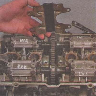
20. We unscrew the four central screws securing the plain bearing caps, install the timing chain damper in place. For the correct orientation of the damper, an arrow with the letter F is stamped on its surface. When installed, it must be oriented forward in the direction of the motorcycle. We tighten the screws.

21. We tighten the bolts of the camshaft bearing caps crosswise with a torque of 12 Nm.
22. Reinstall the cylinder head cover assembly with gasket (the arrow stamped on the top surface of the cover must be oriented forward in the direction of travel of the motorcycle).
23. We wrap the bolts of the cylinder head cover until it stops, without tightening them.
24. We tighten the bolts in several stages in the sequence indicated in the photo with a torque of 10 Nm.
25. Further assembly of the motorcycle is carried out in the reverse order of disassembly.
26. We start the engine, inspect it for leaks.
27. After 400-600 km of run after repair, it is necessary to remove the cylinder head cover and tighten the nuts and bolts of the head to 29 Nm and 12 Nm, respectively.