| PART NUMBER | TOOL NAME |
| B-45523 | VALVE GUIDE REAMER |
| B-45524 | VALVE GUIDE REMOVER/INSTALLER |
| B-45525 | VALVE GUIDE HONE |
| HD-34751 | VALVE GUIDE CLEANING BRUSH |
| HD-39782-A | CYLINDER HEAD SUPPORT STAND |
| HD-39786 | CYLINDER HEAD HOLDING FIXTURE |
| HD-39847 | REAMER T-HANDLE |
| HD-39964 | REAMER LUBRICANT |
Replace valve guides before grinding valve seats. It is the valve stem bore in valve guide that determines valve seat grinding location. If valve stems and/or valve guides are worn beyond service wear limits, install new parts. Refer to Table 3-29.
Removal
Notes:
- Always use cylinder head support stand. Misalignment during valve guide replacement will cause damage to cylinder head valve guide bore.
- Lock ring is present on OEM intake and exhaust valve guides on XR 1200X only.
1. See Figure 3-59. Prepare cylinder head for valve guide replacement.
- a. XR 1200X: Remove and discard lock ring from valve guide groove.
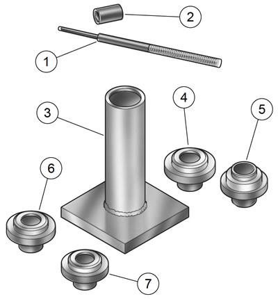
- b. Insert sleeve of intake (4 or 6) or exhaust (5 or 7) seat adapter into tube at top of CYLINDER HEAD SUPPORT STAND (Part No. HD-39782-A) (3).
- c. Position cylinder head so that valve seat is centered on seat adapter.

Figure 3-59. Valve guide replacement tools: 1. Valve guide remover/installer; 2. Installer sleeve; 3. Cylinder head support stand; 4. Intake seat adapter, 883; 5. Exhaust seat adapter, 883; 6. Intake seat adapter, 1200; 7. Exhaust seat adapter, 1200
Note. Do not press out the valve guide from the bottom of the cylinder head. Excessive carbon buildup prevents a proper interference fit for valve guides.
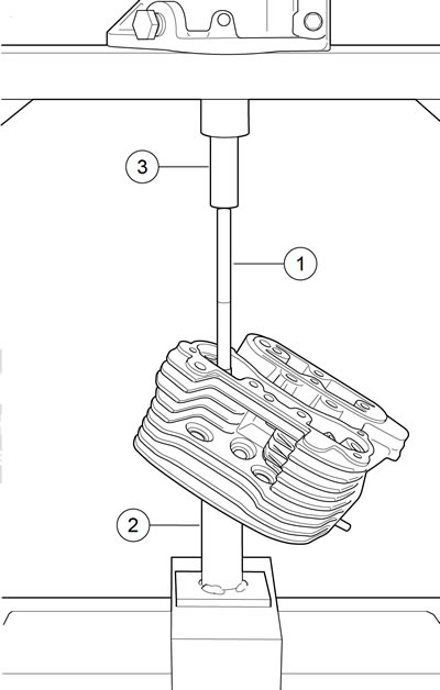
2. See Figure 3-60. At top of the cylinder head, insert VALVE GUIDE REMOVER/INSTALLER (Part No. B-45524) (1) into valve guide bore until tool shoulder contacts end of valve guide.

Figure 3-60. Removing shoulderless valve guide: 1. Valve guide remover/installer; 2. Cylinder head support stand; 3. Ram
Note. See Figure 3-59. Installer sleeve (2) is not used for removal of valve guide.
3. Center VALVE GUIDE REMOVER/INSTALLER under ram (3) of press. Apply pressure until valve guide drops free of cylinder head. Discard valve guide.
Table 3-29. Valve stem clearance/service wear limits
| VALVE | CLEARANCE | SERVICE WEAR LIMIT | ||
| in | mm | in | mm | |
| Intake | 0.001-0.003 | 0.0254-0.0762 | 0.0035 | 0.0965 |
| Exhaust | 0.001-0.003 | 0.0254-0.0762 | 0.0035 | 0.0965 |
Table 3-30. Valve guide remover/installer components
| PART NO | ITEM |
| B-45524 | Valve guide remover/installer with installer sleeve |
| HD-39782-A | Cylinder head support stand |
| HD-39782-2 | Intake seat adapter, 883 |
| HD-39782-3 | Exhaust seat adapter, 883 |
| HD-39782-6 | Intake seat adapter, 1200 |
| HD-39782-7 | Exhaust seat adapter, 1200 |
Installation
1. Check valve guide to valve guide bore clearance.
- a. Measure outer diameter of a new standard valve guide.
- b. Measure the cylinder head valve guide bore. The valve guide diameter should be 0.0020-0.0033 in (0.0508-0.0838 mm) larger than cylinder head valve guide bore.
- c. If interference fit is within specification, a replacement valve guide will be used. If interference fit is not within specification, the cylinder head must be replaced.
2. Measure cylinder head bore and outside diameter of replacement valve guide to verify correct interference fit.
Note. Always use cylinder head support stand. Misalignment during valve guide replacement will cause damage to cylinder head valve guide bore.
3. Prepare cylinder head for valve guide replacement.
- a. See Figure 3-59. Insert sleeve of intake (4 or 6) or exhaust (5 or 7) seat adapter into tube at top of cylinder head support stand (3). Position cylinder head so that valve seat is centered on seat adapter.
- b. Apply petroleum jelly to lightly lubricate external surfaces of valve guide. Spread lubricant so that thin film covers entire surface area.
- c. At top of cylinder head, start valve guide into bore.
- d. Place installer sleeve (2) over valve guide and then insert VALVE GUIDE REMOVER/INSTALLER (1) into installer sleeve.
- e. See Figure 3-61. Center VALVE GUIDE REMOVER/INSTALLER (1) under ram of press and apply pressure only until valve guide is started in bore and then back off ram slightly to allow valve guide to center itself.

Figure 3-61. Installing shoulderless valve guide: 1. Valve guide remover/installer; 2. Installer sleeve; 3. Cylinder head support stand
Note. Always back off ram to allow the valve guide to find center. Pressing valve guide into cylinder head in one stroke can bend remover/installer, break valve guide, distort cylinder head casting and/or damage cylinder head valve guide bore.
- f. Verify that cylinder head support stand (3) and VALVE GUIDE REMOVER/INSTALLER are square. Center VALVE GUIDE REMOVER/INSTALLER under ram and press valve guide further into bore, then back off ram again to allow valve guide to find center.
- g. Repeat previous step and then apply pressure to VALVE GUIDE REMOVER/INSTALLER until installer sleeve (2) contacts machined area of cylinder head surrounding valve guide.
- h. XR 1200X: Install new lock ring into valve guide groove. Make sure that lock ring is square and fully seated in the groove.
4. Secure cylinder head for service.
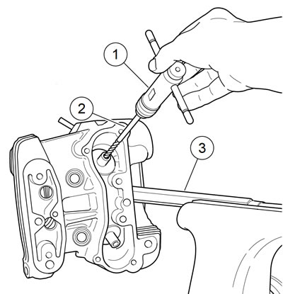
- a. See Figure 3-62. Thread 12 mm end of CYLINDER HEAD HOLDING FIXTURE (Part No. HD-39786) into cylinder head spark plug hole.
- b. Clamp tool in vise at a 45 degree angle or one that offers a comfortable working position.

Figure 3-62. Reaming valve guide bore: 1. T-handle; 2. Valve guide reamer; 3. Holding fixture
Note. Valve guides must be reamed to within 0.0005-0.0001 in (0.013-0.0025 mm) of finished size.
Notes:
- Avoid damage to valve guide bore. Never back reamer out of valve guide.
- For best results, do not push on reamer or apply pressure to the reamer handle. While excessive pressure results in a rough cut, bore will be tapered if pressure is not centrally applied.
5. Obtain the VALVE GUIDE REAMER (Part No. B-45523) (2) and REAMER T-HANDLE (Part No. HD-39847) (1).
- a. Install T-handle on reamer.
- b. Start bit of reamer into bore at top of cylinder head.
- c. Placing thumb on drive socket of REAMER T-HANDLE, apply slight pressure rotating clockwise.
- d. Continue rotating REAMER T-HANDLE until entire bit has passed through valve guide bore and shank of reamer rotates freely.
- e. Remove T-handle from reamer. Carefully pulling on bit, draw shaft of reamer out combustion chamber side of valve guide.
Note. Abrasive particles can damage machined surfaces and plug oil passageways possibly resulting in engine failure.
Warning! Compressed air can pierce the skin and flying debris from compressed air could cause serious eye injury. Wear safety glasses when working with compressed air. Never use your hand to check for air leaks or to determine air flow rates.
6. Direct compressed air into the valve guide bore to remove any metal shavings or debris.
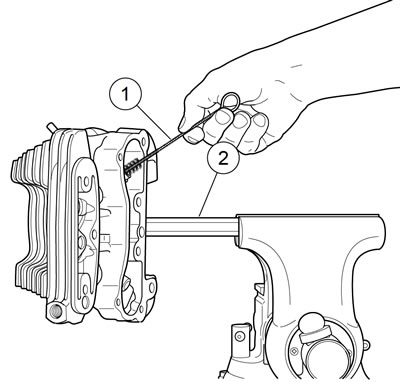
7. See Figure 3-63. Clean valve guide bore with the VALVE GUIDE CLEANING BRUSH (Part No. HD-34751) (1).

Figure 3-63. Scrubbing valve guide bore: 1. Valve guide brush; 2. Cylinder head holding fixture
8. See Figure 3-64. Obtain the VALVE GUIDE HONE (Part No. B-45525) and REAMER LUBRICANT (Part No. HD-39964).
- a. Install hone in a high speed electric drill.
- b. Apply REAMER LUBRICANT to finishing stones of hone and valve guide bore.
- c. Start finishing stones of hone into bore.
- d. Complete 10 to 12 complete strokes using entire length of finishing stone arrangement and drill. Work for a crosshatch pattern of approximately 60 degrees.

Figure 3-64. Honing valve guide bore: 1. Valve guide hone; 2. Cylinder head holding fixture
Note. The hone is not intended for the removal of material.
Note. Abrasive particles can damage machined surfaces and plug oil passageways possibly resulting in engine failure.
Warning! Compressed air can pierce the skin and flying debris from compressed air could cause serious eye injury. Wear safety glasses when working with compressed air. Never use your hand to check for air leaks or to determine air flow rates.
9. Direct low pressure compressed air into the valve guide bore to remove any debris.
10. See Figure 3-63. Clean bore with the VALVE GUIDE CLEANING BRUSH (1).
Note. Always verify valve stem to valve guide clearance after honing, since a worn reamer may cut the bore undersize.
11. Check valve stem to valve guide clearance.
- a. Measure the inside diameter of the valve guide with an inside ball micrometer.
- b. Measure the outside diameter of the valve stem with an outside micrometer.
- c. If valve stem to valve guide clearance is not within specification, the valve stem may be excessively worn orthe valve guide bore undercut. Refer to Table 3-29.
12. Clean cylinder head assembly again.
- a. Using cleaning solvent, thoroughly clean cylinder head and valve guide bore.
- b. Scrub valve guide bore with the VALVE GUIDE CLEANING BRUSH. For best results, use a thin engine oil and clean valve guide bore with the type of swabs or patches found in gun cleaning kits.
- c. Continue to wipe bore until clean cloth shows no evidence of dirt or debris. Follow up with a thorough wash in hot soapy water.
Warning! Compressed air can pierce the skin and flying debris from compressed air could cause serious eye injury. Wear safety glasses when working with compressed air. Never use your hand to check for air leaks or to determine air flow rates.
13. Blow parts dry with low pressure compressed air.
