Warning!
- Execute the troubleshooting on each malfunction from [A] to [D] in sequence.
- Use the sufficiently charged regular batteries only.
[A] Malfunction check by the ABS warning light
[B] Detail check of malfunction
Results by self diagnosis are displayed by the multi-function display or a pocket tester according to the ECU’s operation.
[C] Supposing the malfunction cause and position
Find the malfunction cause by reasoning the place and situation where it occurred.
[D] ABS system services
Execute the final check after disassembly and assembly.
Warning! Perform the troubleshooting [A] → [B] → [C] → [D] in order. Be sure to follow the order since it results in the wrong diagnosis if the order is differently taken or omitted.
Basic process for troubleshooting
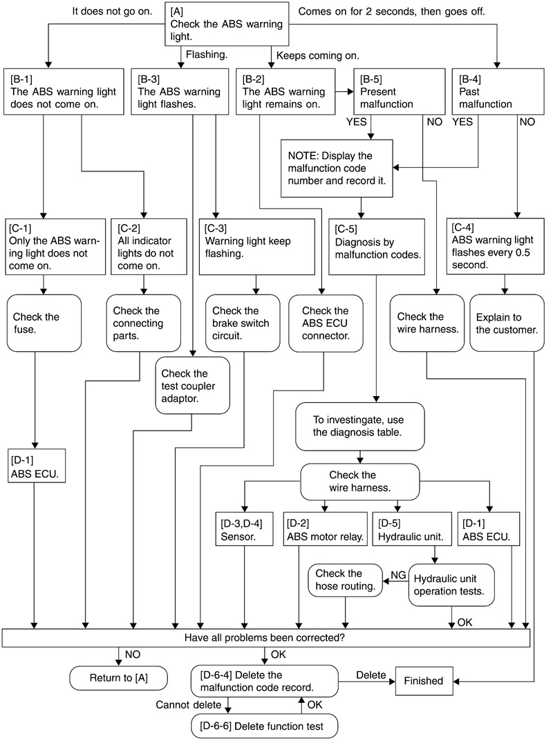
Note: Do not delete the malfunction code during the troubleshooting procedures. Be sure to delete it when the service is finished.
Warning! Always execute the «final check» when the components related to ABS are checked and serviced.
[A] ABS malfunction check using the ABS warning light
Turn the main switch to «ON». (Do not start the engine).
- 1. The ABS warning light does not come on. [B-1]
- 2. The ABS warning light remains on. [B-2]
- 3. The ABS warning light flashes. [B-3]
- 4. The ABS warning light comes on for 2 seconds, then goes off. [B-4]
[B] Detailed ABS malfunction check
[B-1] The ABS warning light does not come on
Do other indicators operate normally?
- 1. Yes [C-1]
- 2. No [C-2]
[B-2] The ABS warning light remains on
Note: Check following the steps in sequence.
1. Battery voltage low.
Charge, inspect or replace the battery.
2. Malfunction codes displayed. Check the malfunction codes using the ABS test coupler adaptor. Perform troubleshooting corresponding to the malfunction codes. [B-5]
3. Wire harness, ABS ECU and meter coupler are disconnected.
Connect the coupler securely until a «click» sound is heard.
4. Check the disconnection between the ABS ECU and meter (ABS warning light).
Check the conductivity of the wire harness and repair or replace the failure part.
5. Meter circuit malfunction.
Check by the following procedures.
- 1. Remove the ABS ECU and connect the ABS test coupler adaptor.
- 2. Connect the white/red lead from the test coupler adaptor to the GND terminal and set the main switch to «ON».
- 3. Does the ABS warning light go off?
- 1. Yes → Replace the ABS ECU.
- 2. No → Replace the meter.
[B-3] The ABS warning light flashes
Note: Check the battery voltage before proceeding.
Check the test coupler located in the left inner panel (front cowling). Is the T/C terminal ground?
1. Yes → Disconnect the grounding lead from the T/C terminal and install the protective cap onto the test coupler.
Note: When the test coupler adaptor is connected to test coupler, the T/C terminal is grounded.
2. No → [C-3]
Arrangement and the function of test couplers
- ECU becomes the malfunction diagnostic mode when the T/C terminal is grounded.
- Malfunction code which the ECU generated in the malfunction diagnostic mode (rise and fall of voltage) is output at the T/F terminal.
- ABS warning light terminal is used when checking the ABS warning light circuit.
- To ground the T/C terminal, connect the test coupler adapter «A» with the test coupler. Before connecting, check if the battery is sufficiently charged.
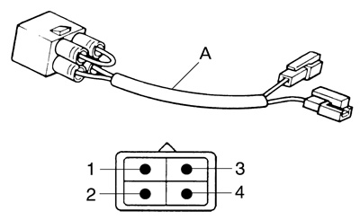
[B-4] Malfunction check by the ABS self diagnosis (past malfunction)
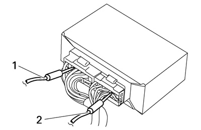
Remove the side cowling (left) and check the location of test coupler «1». Remove the protective cap and connect the ABS test coupler adapter «2» to the test coupler. The T/C terminal (sky-blue) is now connected to the ground.
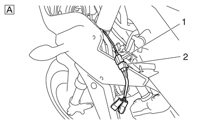
A. FZ1-SA | 
B. FZ1-NA |
1. Indicate the malfunction code (Example: malfunction code 11).

2. ABS warning light flashes every 0.5 second for more than 6 seconds → [C-4, C-5].
If the ABS warning light flashes every 0.5 second, the malfunction code of a past malfunction has not been stored in the memory of the ECU (ABS). If a malfunction code is displayed on the multifunction display, the ABS warning light flashes. Make sure that the customer understands the possible conditions when the ABS warning light comes on.
[B-5] Malfunction check by the ABS self diagnosis (present malfunction)
Note: Before proceeding to read the part of «Arrangement and the function of test coupler».
Remove the side cowling (left) and check the location of test coupler. Connect the test coupler adapter with the test coupler in order to ground the T/C terminal (sky-blue). (Figure-«A») Set the range of pocket tester to DC 20 V. Connect the negative (-) terminal of tester to the T/F terminal (light green) and positive (+) terminal to the positive (+) terminal of battery. (Figure-«B») Read the tester indication. (Figure-«C»)
Note: Read the code through this means so that the «currently malfunction» code is not indicated on the meter.
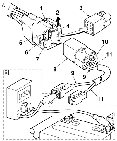
1. ABS test coupler; 2. Lock plate; 3. Protective cap; 4. Grounding; 5. T/C terminal; 6. T/F terminal; 7. ABS warning light terminal (White/Red); 8. Test coupler adapter; 9. Light green; 10. Black; 11. White/Red
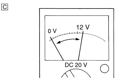
As an example, «10 digits/1 digit pattern» of tester reading is shown below.

A. This example is the pattern which shows malfunction code 12
C. Time (second)
B. This example is the pattern which shows malfunction code 21
[C] Determining the cause and location of the malfunction
[C-1] Only the ABS warning light does not come on when the main switch is set to «ON»
1. Confirmation using the test coupler adaptor.
Connect the test coupler adapter to the test coupler.
Note: Check following the steps in sequence.
1. Wire harness is short-circuited to GND between the ABS ECU and meter (ABS warning light). Check by the following procedures.
- 1. Remove the ABS ECU and meter, and connect the ABS test coupler adaptor.
- 2. Check the conductivity between the white/red lead of test adaptor and GND.
- 3. If there is conductivity, the trouble is caused by the wire harness short-circuit. Repair or replace the failure part.
2. Meter circuit malfunction.
- 1. Remove only the ABS ECU from the connector.
- 2. If the ABS warning light comes on when the main switch is turned «ON», the meter is normal. It means the ABS ECU malfunction. Replace the ECU.
[C-2] ABS warning light and all other indicators do not come on
Note: Check following the steps in sequence.
1. Check the power supply system.
- 1. Check that the battery is connected correctly.
- 2. Check the battery voltage. (Refer to «Checking and charging the battery»).
- 3. Check if the main fuse is blown. If the main fuse is blown, determine the cause and repair. Replace with a new fuse. (Refer to «Checking the fuses»).
2. Check the connections.
- 1. Check that the main fuse coupler is securely connected.
- 2. Check that the main switch coupler is securely connected.
- 3. Check that the meter assembly coupler is securely connected. (Refer to «Abs connector location chart»).
- When these checks are finished, return to [A] and check the ABS again.
[C-3] ABS warning light flashes
1. When the warning light flashes «ON» for 0.25 seconds and «OFF» for 0.75 seconds, check the stop switch or 3-4), 5).
2. When the warning light flashes «ON» for 0.75 seconds and «OFF» for 0.25 seconds, the starter motor monitor is defective. Same as the error code 22 or 3-1), 2), 3).
3. When the warning light flashes «ON» for 1 second and «OFF» for 1 second, it is another malfunction. Same as the error code 28. The following are probable causes to explain why the ABS warning light flashed while riding and then stopped flashing or stopped flashing when main switch was set «OFF» to «ON».
- 1. The rear wheel was rotated with the vehicle on the centerstand. → The system is normal.
- 2. The rear wheel was raced. → The system is normal.
- 3. The vehicle was ridden on the rear wheel with the front wheel elevated. → The system is normal.
- 4. The vehicle was ridden on extremely uneven roads continuously. → The system is normal.
- 5. The brake switch is defective or improperly adjusted. → Replace or adjust.
[C-4] ABS warning light flashes every 0.5 second
If the ABS warning light flashes every 0.5 second, the malfunction code of a past malfunction has not been stored in the memory of the ABS ECU. If a malfunction code is displayed on the multifunction display, the ABS warning light flashes. Make sure that the customer understands the possible conditions when the ABS warning light comes on.
1. Voltage drop.
For the ABS to operate correctly, the voltage should be always higher than the specified voltage. If the voltage drops to lower than 10 V, the ABS warning light comes on and the ABS does not operate. When the voltage recovers to higher than 10 V, the ABS operates. However, the magneto, battery and rectifier/regulator must be checked. Follow the regular procedures for service of the power supply system.
2. ABS is stopped by the ABS ECU.
The ABS ECU may stop the ABS operation if it is exposed to extremely strong electromagnetic waves or static electricity. When the ABS ECU is no longer exposed to the electromagnetic waves, static electricity, and the ABS warning light is not flashing, there is no effect on the operation of the ABS. Explain to the customer that the ABS will operate normally.
[C-5] Diagnosis by the malfunction code
Malfunction codes are used to determine the malfunctions that have occurred. (Refer to «[B-4] MALFUNCTION CHECK BY THE ABS SELF-DIAGNOSIS (PAST MALFUNCTION)» and «[B-5] MALFUNCTION CHECK BY THE ABS SELF-DIAGNOSIS (PRESENT MALFUNCTION)»). The malfunction codes are explained in the following table.
Note: Record all of the malfunction codes displayed and check the check points.

* Malfunction code 11 is indicated if the rear wheel rotates for more than 20 seconds with the front wheel stopped.
Note: Malfunction code 15 (front wheel sensor) or 16 (rear wheel sensor) is displayed if a defective connection to either the front or rear sensor is detected whether or not the vehicle is ridden.
Malfunction code 11 (Front wheel sensor signal is not received properly)
Turn the main switch to «OFF», then back to «ON» after removing the test coupler adapter.
1. ABS warning light remains on.
- → Defective connection in the front wheel sensor circuit.
- Front wheel sensor coupler is disconnected. → [D-3]
- Front wheel sensor lead or internal circuit is broken. → [D-3]
- Wire harness (ABS) sensor circuit is broken. → (Refer to «Circuit diagram (fz1-sa)»).
- ABS ECU coupler terminal is disconnected. → [D-1]
2. ABS warning light goes on for 2 seconds then goes off.
- 1. With the front wheel stopped, the rear wheel was rotated for more than 20 seconds. This is not a malfunction.
- 2. Signal is not generated at the front wheel sensor.
- Front wheel sensor is not installed properly. → [D-3]
- Front wheel sensor rotor is defective. → [D-3]
- 3. Front wheel sensor circuit is short-circuited.
- Front wheel sensor or lead is short-circuited. → [D-3]
- Wire harness (ABS) sensor circuit is short-circuited. → (Refer to «Circuit diagram (fz1-sa)»).
- 4. Front wheel sensor output drops.
- Sensor signal output may drop due to failure on bearings, wheel axle, wheel or sensor housing of front wheel. Check these components when installed for looseness, distortion, and bends.
- Malfunction code 12 (Rear wheel sensor signal is not received properly).
- Turn the main switch to «OFF», then back to «ON» after removing the test coupler adapter.
- 1. ABS warning light remains on.
- → Defective connection in the rear wheel sensor circuit.
- Rear wheel sensor coupler is disconnected. → [D-4]
- Rear wheel sensor lead or internal circuit is broken. → [D-4]
- Wire harness (ABS) sensor circuit is disconnected. → (Refer to «Circuit diagram (fz1-sa)»).
- ABS ECU coupler terminal is disconnected. → [D-1]
2. ABS warning light goes on for 2 seconds then goes off.
- 1. With the rear wheel stopped, the front wheel was rotated at a speed faster than 11 km/h. This is not a malfunction.
- 2. Signal is not generated at the rear wheel sensor.
- Rear wheel sensor is not installed properly. → [D-4]
- Rear wheel sensor rotor is defective. → [D-4]
- 3. Rear wheel sensor circuit is short-circuited.
- Rear sensor or lead is short-circuited. → [D-4]
- Wire harness (ABS) sensor circuit is short-circuited. → (Refer to «Circuit diagram (fz1-sa)»).
- 4. Rear wheel sensor output drops.
- Sensor signal output may drop due to failure of the bearing, wheel, or brake caliper bracket of the rear wheel. Check these components when installed for looseness, distortion, and bends.
Note: If the vehicle is ridden on extremely uneven roads continuously, the ABS warning light may flash and malfunction code 11 or 12 may be recorded depending on the condition.
Malfunction code 13 (front wheel) and malfunction code 14 (rear wheel) (Incorrect signal is detected by the front (13) or rear (14) wheel sensor).
1. The wheel sensors or sensor rotors are not properly installed.
- 1. Installation of the front or rear wheel sensor
- Check that the wheel sensor is properly installed in the housing. → [D-3, 4]
- Check if there is looseness between the housing and the front wheel. → [D-3, 4]
- Check if there is looseness rear brake caliper bracket and the rear wheel. → [D-3, 4]
- 2. Installation of the front or rear wheel sensor rotor
- Check that the sensor rotor is correctly pressed in the front wheel. → [D-3, 4]
- Check that the sensor rotor is correctly install to the rear wheel. → [D-3, 4]
- Check the rotor and inside the rotor housing for foreign materials. → [D-3, 4]
2. Teeth surfaces of the sensor rotors are defective.
- Check for flaws on the teeth surfaces of the front or rear wheel sensor rotors.
- Also, check for any foreign materials. → [D-3, 4]
3. Sensor output has dropped.
- Sensor signal output may drop due to failure of the bearings, wheel axle, rear brake caliper bracket wheel or sensor housing of (front) the front or rear wheel. Check these components when installed for looseness, distortion, and bends.
Malfunction code 15 (front wheel sensor) and malfunction code 16 (rear wheel sensor) (No continuity in the front or rear wheel sensor circuits).
Broken front or rear wheel sensor circuit is detected.
- Front or rear wheel sensor coupler is broken. → [D-3, 4]
- Front or rear wheel sensor or lead is broken. → [D-3, 4]
- Sub-wire harness (ABS) sensor circuit is broken. → (Refer to «Circuit diagram (fz1-sa)»).
- Sub-wire harness (ABS) is disconnected from the ABS ECU coupler terminal. → [D-1]
Notes:
- Check that both the front and rear wheel sensor couplers are connected securely.
- If the vehicle is ridden after malfunction code 15 (front wheel sensor) or 16 (rear wheel sensor) is displayed, the malfunction code will be overwritten from 15 to 11 (front wheel sensor signal) or from 16 to 12 (rear wheel sensor signal).
1. Check the wheel sensor signal
- Measure the wheel sensor signal output voltage. Refer to «CHECKING THE WHEEL SENSOR» on page 8-149.
2. Check the appearance.
3. Check the wire harness.
- 1. Disconnection of the ABS ECU coupler terminal
- 2. Remove the ABS ECU coupler and wheel sensor coupler and check the conductivity, shortcircuit to GND and short-circuit to SSR-VCC from the wire harness.
- Conductivity of the wire harness
- Check the conductivity between «A»-«B», and «C»-«D».
- GND short-circuit
- Check the short-circuit to GND between «A»-«B», and «C»-«D».
- Short-circuit between the wire harnesses
- Check the short-circuit between «A»-«C», and «B»-«D».
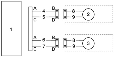
1. ABS ECU; 2. Front wheel sensor; 3. Rear wheel sensor; 4. Blue; 5. Blue/White; 6. Blue/Red; 7. Blue/Black; 8. White; 9. Gray
4. When the items «1» to «4» are normal, replace the wheel sensor.
5. Replace the ABS ECU if the condition does not become normal even if the wheel sensor is replaced.
Malfunction code 18 (Missing serration of sensor rotor)
1. Missing serration of the rear sensor rotor.
- Replace the rear sensor rotor.
Malfunction code 21 (Disconnection and short-circuit of hydraulic unit solenoid).
1. Hydraulic unit solenoid coupler.
- Check if the hydraulic unit solenoid coupler terminal is disconnected. (Refer to «Abs connector location chart»).
- Check the front and rear wheel solenoids for continuity → [D-5]
- Check the insulation of all solenoid terminals and the negative battery terminal. → [D-5]
3. Wire harness (ABS).
- Check the hydraulic unit solenoid circuits for continuity. (See the illustration below). Continuity between: «A»-«B», «A»-«C», «D»-«G», «E»-«F».
- Check the insulation of the hydraulic unit solenoid circuits and the negative battery terminal.
4. Battery.
- Battery terminal is disconnected
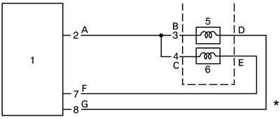
1. ABS ECU; 2. Red; 3. Red; 4. Red; 5. Front solenoid; 6. Rear solenoid; 7. Green; 8. White/Red
Malfunction code 22 (Starter motor monitor malfunction)
1. Disconnection of the wire harness for the start system circuit
- → Check the conductivity of the wire harness and repair or replace the failure part.
2. Disconnection of the starter motor monitor
- → Check the conductivity of the wire harness and repair or replace the failure part.
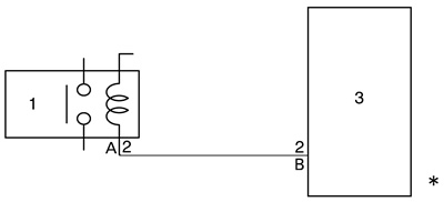
1. Starter relay; 2. Blue/White
* Continuity between: «A»-«B».
Note: If you do not start the engine with the starter switch but repeat push-starting the engine excessively, this code may be input.
Malfunction code 24 (Step light failure [Brake system circuit has failure]).
1. Disconnection of the wire harness for the brake circuit.
- → Check the conductivity of the wire harness and repair or replace the failure part.
2. Disconnection of the stop lamp monitor.
- → Check the conductivity of the wire harness and repair or replace the failure part.

1. Front brake light switch; 2. Rear brake light switch; 3. Green/Yellow; 4. Yellow; 5. Yellow; 6. Brake light; 7. Yellow; 8. ABS ECU
* Continuity between: «A»-«B».
Malfunction code 25 (At the beginning of running, there is no pulse from the front wheel sensor).
- Rear wheel was rotated with the vehicle on the stand.
- Rear wheel was wheel-spin.
- Wheel tried.
- Defective installation of the wheel speed sensor for the front wheel.
Malfunction code 28 (Other malfunctions [Malfunction of the memory in ABS ECU]).
1. Other malfunctions.
- → Replace the ABS ECU.
Malfunction code 31 (Disconnection is detected between the battery and the ABS ECU system).
Note: Check following the steps in sequence.
1. ABS motor fuse blown.
- Replace the ABS motor fuse.
2. Coupler joint between the battery and ABS ECU.
- Connect the coupler securely until a «click» sound is heard.
3. Disconnection of the wire harness between the battery and ABS ECU.
- Check the conductivity of the wire harness and repair or replace the failure part.
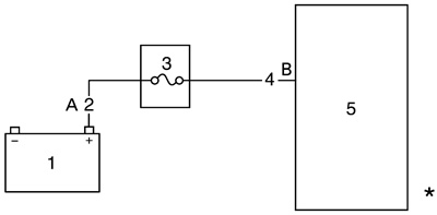
1. Battery; 2. Red; 3. ABS motor fuse; 4. Brown; 5. ABS ECU
* Continuity between: «A»-«B».
4. When the items 1 to 3 are normal, replace the ABS ECU.
Malfunction code 32 (Circuit malfunction of ABS ECU is detected. Upstream side of the solenoid relay).
Note: Check following the steps in sequence.
1. Short-circuit between the battery positive terminal and fail safe relay monitor terminal
- Check the conductivity of the wire harness and repair or replace the failure part.
2. Short-circuit between the battery ignition terminal and fail safe relay monitor terminal
- Check the conductivity of the wire harness and repair or replace the failure part.

1. Battery; 2. Red; 3. Main switch; 4. Brown/White; 5. ABS ECU; 6. Red; 7. Red; 8. To HU
* Continuity between: «A»-«C», «B»-«C».
3. When the items 1 to 2 are normal, replace the ABS ECU.
Malfunction code 33 (Defective operation of the ABS motor is detected. [ABS motor stops and will not rotate]).
Note: Check following the steps in sequence.
1. ABS motor fuse.
- Check if the ABS motor fuse beside the battery is blown.
2. ABS motor relay.
- Check if the ABS motor relay operates correctly. → [D-2]
3. Wire harness.
- Remove the ABS motor relay and the ABS motor fuse, and then check for continuity between the brown (Refer to «Abs connector location chart» in ABS motor relay coupler drawing). terminal of the wire harness (ABS) and the wire harness (ABS) end (terminal A shown in the illustration) of the ABS motor fuse terminal beside the battery. (Refer to «Circuit diagram (fz1-sa)»).
- Check for continuity between the positive battery terminal and the battery end of the ABS motor fuse terminal (terminal «B» shown in the above illustration).
- Remove the ABS ECU and the ABS motor relay from the wire harness (ABS), and then check for continuity between the white/black lead terminals of ABS ECU coupler and the white/red lead terminals of ABS motor coupler.
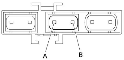
A. Terminal A; B. Terminal B
Malfunction code 34 (Defective operation of the ABS motor is detected. [ABS motor keeps running and will not stop.])
Check the following:
- 1. ABS motor
- Check if the ABS motor coupler located under the fuel tank is connected properly.
- Check the ABS motor for continuity. → [D-5]
- 2. Wire harness (ABS)
- Remove the ABS motor coupler and check for continuity between the black terminal of the ABS motor coupler of the wire harness (ABS) and the negative battery terminal.
- Remove the ABS ECU coupler and check for continuity between the red/white terminal of the ABS ECU coupler and the red/white terminal of the aBs motor coupler. → [D-1]
- Remove the ABS motor relay and check for continuity between the red/white terminal of the ABS motor coupler of the wire harness (ABS) and the positive battery terminal.
- 3. ABS motor relay
- Check if the ABS motor relay operates correctly. → [D-2]
Malfunction code 35 (Disconnection is detected between the ABS ECU and solenoid system. Downstream side of the solenoid relay).
1. Disconnected coupler between the ABS ECU and HU solenoid
- Connect the coupler securely until a «click» sound is heard.
2. Disconnection of the wire harness between the ABS ECU and HU solenoid
- Check the conductivity of the wire harness and repair or replace the failure part.
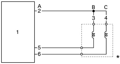
1. ABS ECU; 2. Red; 3. Red; 4. Red; 5. Green; 6. White/Red
* Continuity between: «A»-«B», «A»-«C».
3. Battery terminal is disconnected.
4. When the items 1 to 3 are normal, replace the ABS ECU.
Malfunction code 41 (Front wheel will not recover from the locking tendency even though the signal is continuously transmitted from the ABS ECU to release the hydraulic state [when the battery voltage is normal]).
Check the following:
- 1. Rotation of the front wheel
- Check that there is no brake disc drag on the front wheel and make sure it rotates smoothly.
- Check the front wheel axle for loose bearings and bends, and the brake disc for distortion.
- 2. Brake master cylinder and brake caliper
- Check that the brake fluid pressure is correctly transmitted to the brake caliper when the brake lever is operated and that the pressure decreases when the lever is released.
- 3. Brake fluid
- Visually check the brake fluid in the brake master cylinder reservoir and the fluid for water, foreign materials, solidification and contamination.
- Check for air in the brake hose lines.
- 4. Brake hose lines
- Check the brake hose lines for kinks and deterioration.
- Check that the connections of the brake hose lines from the brake master cylinder to the hydraulic unit and to the front brake caliper from the hydraulic unit are correct.
Warning! Only use genuine Yamaha parts. Using other brake pipes, hoses and union bolts may close the brake hose lines.
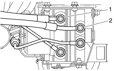
Warning! The front brake will not function properly if the connections are reversed.
- Front brake hose «1» inlet: from the front brake master cylinder
- Front brake hose «2» outlet: to the front brake caliper
Notes:
- If the front brake hose inlet and outlet connections are reversed on the hydraulic unit, the brake lever is pulled to full stroke without responding and will be pushed back slowly without pulsating when the final check in [D-6] is performed.
- If the front and rear brake hose connections are reversed on the hydraulic unit, the pulsating action in the brake lever and brake pedal will be performed in the reverse order when the final check in [D-6] is performed.
5. Hydraulic unit solenoid coupler terminal.
- Check if the front and rear hydraulic unit solenoid coupler terminals (hydraulic unit and wire harness [ABS]) are reversed.
| Terminal color | ||
| Solenoid side | Wire harness side (ABS) | |
| Front | Red, Green | Red, Green |
| Rear | Red, Blue | Red, White/Red |
6. Hydraulic unit.
If the malfunction is not corrected after performing steps 1 to 5, replace the hydraulic unit. Be sure to connect the brake hoses and couplers correctly and securely. Check the hydraulic unit operation. (Refer to «[D-6] FINAL CHECK» on page 8-130).
Malfunction code 42 (Rear wheel not recover from the locking tendency even though the signal is continuously transmitted from the ABS ECU to release the hydraulic state [when the battery voltage is normal]).
Check the following:
- 1. Rotation of the rear wheel
- Check that there is no brake drag on the rear wheel and make sure it rotates smoothly.
- Check for brake disc distortion.
- 2. Brake master cylinder and brake caliper
- Check that the brake fluid pressure is correctly transmitted to the brake disc when the brake pedal is operated and that the pressure decreases when the pedal is released.
- 3. Brake fluid
- Visually check the brake fluid in the brake master cylinder reservoir and check the fluid for water, foreign materials, solidification and contamination.
- Check for air in the brake hose lines.
- 4. Brake hose lines
- Check the brake hose lines for kinks and deterioration (particularly between the hydraulic unit and the rear brake caliper).
- Check that the connections of the brake hose lines from the brake master cylinder to the hydraulic unit and to the rear brake caliper from the hydraulic unit are correct.
Warning! Only use genuine Yamaha parts. Using other brake pipes, hoses and union bolts may close the brake hose lines.
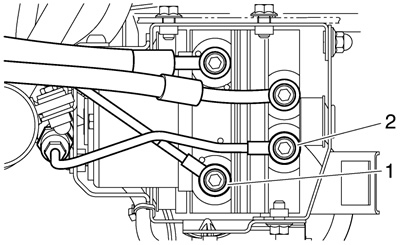
Warning! The rear brake will not function properly if the connections are reversed.
- Rear brake hose «1» inlet: from the rear brake master cylinder
- Rear brake hose «2» outlet: to the rear brake caliper
Notes:
- If the rear brake hose inlet and outlet connections are reversed on the hydraulic unit, the brake pedal is pressed down to full stroke without responding and will be pushed back slowly without pulsating when the final check is performed.
- If the front and rear brake hose connections are reversed on the hydraulic unit, the pulsating action in the brake lever and brake pedal will be performed in the reverse order when the final check is performed.
5. Hydraulic unit solenoid coupler terminal.
- Check if the front and rear hydraulic unit solenoid coupler terminals (hydraulic unit and wire harness [ABS]) are reversed.
| Terminal color | ||
| Solenoid side | Wire harness side (ABS) | |
| Front | Red, Green | Red, Green |
| Rear | Red, Blue | Red, White/Red |
6. Hydraulic unit.
- If the malfunction is not corrected after performing steps 1 to 5, replace the hydraulic unit. Be sure to connect the brake hose lines and couplers correctly and securely. Check the hydraulic unit operation. (Refer to «[D-6] FINAL CHECK» on page 8-130).
Malfunction code 51 (Front wheel will not recover from the locking tendency even though the signal is continuously transmitted from the ABS ECU to release the hydraulic state [when the battery voltage is low]).
Check the following:
- 1. Rotation of the front wheel. Refer to «Malfunction code 41».
- 2. Brake master cylinder and brake caliper. Refer to «Malfunction code 41».
- 3. Brake fluid. Refer to «Malfunction code 41».
- 4. Brake hose lines. Refer to «Malfunction code 41».
- 5. Hydraulic unit solenoid coupler terminals. Refer to «Malfunction code 41».
- 6. Hydraulic unit. Refer to «Malfunction code 41».
- 7. Battery voltage. Measure the battery voltage.
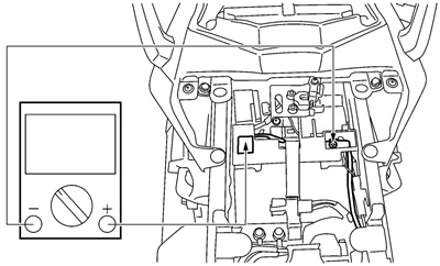
Malfunction code 52 (Rear wheel will not recover from the locking tendency even though the signal is continuously transmitted from the ABS ECU to release the hydraulic state [when the battery voltage is low]).
Check the following:
- 1. Rotation of the rear wheel. Refer to «Malfunction code 42».
- 2. Brake master cylinder and brake caliper. Refer to «Malfunction code 42».
- 3. Brake fluid. Refer to «Malfunction code 42».
- 4. Brake hose lines. Refer to «Malfunction code 42».
- 5. Hydraulic unit solenoid coupler terminals. Refer to «Malfunction code 42».
- 6. Hydraulic unit. Refer to «Malfunction code 42».
- 7. Battery voltage. Measure the battery voltage.

Malfunction code 61 (front), 62 (rear) (Sensor power supply is low)
1. Battery voltage low.
- Charge, check or replace the battery.
2. Battery terminal is disconnected.
- Malfunction code 63 (front), 64 (rear) (Sensor power supply failure)
1. GND short-circuit of the wire harness.
- Remove the ABS ECU coupler and wheel sensor coupler and check the conductivity between the wire harness and GND.
- If short-circuit is detected, replace the wire harness because the cause is the wire harness failure.
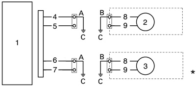
1. ABS ECU; 2. Front wheel sensor; 3. Rear wheel sensor; 4. Blue; 5. Blue/white; 6. Blue/Red; 7. Blue/Black; 8. White; 9. Gray
* Continuity between: «A»-«C», «B»-«C».
2. Wheel sensor malfunction.
- Check the conductivity between the wheel sensor leads (white) and GND.
- If short-circuit is detected, replace the wheel sensor because the cause is the wheel sensor failure.
3. Battery terminal is disconnected.
4. When the items 1 to 3 are normal, replace the ABS ECU.
[D-6-4] Deleting the malfunction code
1. Connect the test coupler adapter «1» to the test coupler «2». Refer to «[B-5] MALFUNCTION CHECK BY THE ABS SELF DIAGNOSIS (PRESENT MALFUNCTION)».

A. FZ1-SA | 
B. FZ1-NA |
2. Turn the main switch on.
- The multi-function display indicates previously recorded malfunction codes.
Note: The ABS error code is not displayed during the diagnosis of the fuel injection.
3. Turn the engine stop switch off.
Caution: If the starter switch is pushed without turning the engine stop switch off, it may damage the starting motor gears or other parts, therefore be sure to turn it off.
4. Push the starter switch more than 10 times in 4 seconds to delete the malfunction codes.
Note: If the malfunction codes cannot be cleared, the disconnection of the starter switch monitor leads could be a cause.
5. Turn the main switch off.
6. Turn the main switch on again.
- Check that the ABS warning light goes on for 2 seconds, then goes out for 3 seconds and starts flashing.

a. ABS warning light; b. ON; c. Main switch on; d. Main switch off; e. Flashing; f. 2 seconds; g. 3 seconds; h. 0.5 seconds
7. Turn the main switch off.
8. Disconnect the test coupler adapter from the test coupler, and install the protective cap with the test coupler adapter. Deleting the malfunction code is now finished.
Note: Do not forget to install the protective cap.
Caution: Since the ECU remains in the memory until the malfunction code is deleted, always delete the malfunction code when the service work is finished.
[D-6-6] Delete function test
1. Place the vehicle on the sidestand.
2. Set the main switch to «OFF».
3. Connect the test coupler adapter to the test coupler.
4. Set the main switch to «ON».
5. Check:
- ECU voltage
- Connect the pocket tester (DC 20 V) to the ECU coupler.
- Tester positive probe → Brown/White «1»
- Tester negative probe → Black/White «2»
Battery voltage: Higher than 12.8 V.
Lower than 12.8 V → Charge or replace the battery.

6. Check:
- ECU-to-start-switch-lead continuity
- Connect the pocket tester (Ω x 1) to the ECU coupler and start switch coupler.
- Tester positive probe → Blue/White «1» (start switch)
- Tester negative probe → Green/White «2» (ECU)
- No continuity → Replace or repair the wire harness.
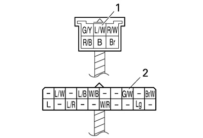
7. Check:
- ECU voltage
- Connect the pocket tester (DC 20 V) to the ECU coupler.
- Tester positive probe → Green/White «1»
- Tester negative probe → Black/White «2» Push the start switch.
Start switch ON: less than 1 V.
Start switch OFF: more than 12 V.
Out of specification → Replace the handlebar switch.
8. If the above-mentioned check are within specification, replace the ECU.
[D-6] Final check
Checking procedures:
- 1. Check the brake fluid level in the brake master cylinder reservoir and brake fluid reservoir. Refer to «CHECKING THE BRAKE FLUID LEVEL» on page 3-23.
- 2. Check the wheel sensor housings and wheel sensors for proper installation. Refer to «Installing the front wheel» and «INSTALLING THE REAR WHEEL» on page 4-24.
- 3. Perform hydraulic unit operation test 1 or 2. Refer to «Hydraulic unit operation test».
- 4. Delete the malfunction codes. Refer to «[D-6-4] DELETING THE MALFUNCTION CODE» on page 8-128.
- 5. Perform a trial run. Refer to «[D-6-5] TRIAL RUN» on page 4-57.
