
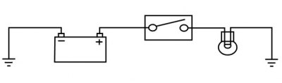
Basic circuit diagram
In the above circuit an electrical reservoir (the battery) is connected via a cable to a terminal on the controlling device (the switch) whose contacts are either open or closed. The other terminal on the switch is connected via a cable to the consumer (the bulb), and the other side of the bulb filament is connected to ground (earth) by another cable. The ground point is usually a part of the frame or engine, to which the battery negative terminal is also connected.
When the switch contacts are open (as shown in the diagram), the circuit is broken and no current flows. When the switch contacts are closed, the circuit is made and current flows from the battery positive terminal through the switch contacts and bulb filament to ground. The frame completes the circuit to the battery negative terminal and the bulb illuminates.
Although some circuits on the circuit diagram may at first seem more complicated, it will generally be found that they can be broken down into sections which do not differ greatly from the basic circuit above.
Circuit diagrams
Circuit diagrams are created to provide a 'picture' of the electrical system and to identify the route taken by each individual wire through the system, in order to identify which components it feeds and which connectors the wire runs through. Circuit diagrams are an essential tool for fault finding, as it is possible to locate start and finish points for a circuit without having to manually trace the wire through the motorcycle itself. Circuits diagrams may look confusing at first but when they are studied closely they soon become logical.
Due to the complex circuits and the number of individual wires, Triumph uses two types of circuit diagram in its Service Manuals.
- Within the manual, conventional circuit diagrams are used to show the layout of the main circuits of the motorcycle. These are: Engine management/ignition, Lighting, Starting and Charging and Auxiliary and Accessory. In these diagrams no attempt is made to show the components of the system in any particular order or position in relation to the motorcycle.
- At the back of the Service Manual a full colour layout circuit diagram is used to show the main electrical components in a position similar to the actual position on the motorcycle.
Both of these circuit diagrams use similar symbols to illustrate the various system components and will be accompanied by a key indicating circuit diagram components and wiring colour codes.
Circuit diagrams also depict the inner workings of a switch housing (i.e. which wire connects to which when a switch is turned from one position to another) so that a test of that switch can be made using the wire terminals in the connector instead of disassembling the switch itself.
Tracing circuits
The following is a description of two types of common electrical failures, and some of the methods which may be used to find them.
Open circuit
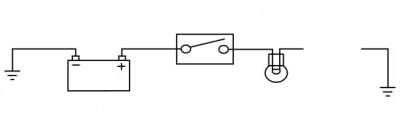
A break in an electrical circuit - current cannot flow. Usually caused by a break in a wire or cable or by a loose connection. Open circuits can often be intermittent, making diagnosis difficult.
Short circuit
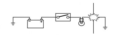
A 'short cut' in an electrical circuit - current bypasses the intended circuit, either to ground or to another, different circuit. Often caused by failure of the cable insulation due to chafing or trapping of the wire. There are two different types of short circuit - short to ground and short to battery Voltage.
A short to ground means that the current is going to ground before it reaches the component it is supposed to feed. These are often caused by chafing of the harness to the frame or wires trapped between a bolted component, and will often blow the fuse on that circuit.
A short to battery voltage (12 Volts) is caused by a live power supply wire contacting an adjacent cable. Note that it is also possible for a 5 Volt sensor reference voltage to short to an adjacent circuit, which can also cause electrical failures and DTCs (Diagnostic Trouble Code) to be stored.
When tracing a wire that is suspect, carefully check the circuit diagram before starting. Remember:
- a wire may diverge at a splice and go off to feed other circuits. If these circuits are working, check for wiring faults from the splice onwards.
- the circuit diagram is not an accurate guide to the actual location of the parts when fitted on the motorcycle. It is a schematic diagram of the circuits.
- particularly where engine management items are concerned, the circuit is only completed by the ECM. If the ECM is not connected, the circuit may register as open.
To check continuity:
Caution! Ensure the circuit being tested is switched off before measuring continuity. Damage to the Digital Multi Meter (DMM) may result from testing a 'live' circuit with the meter set to resistance (Ω).
In the example below, the ground circuit continuity is being tested from the battery to the frame.

- Locate each end of the wire.
- Set the Digital Multi Meter (DMM) to resistance check Ohms.
- Probe each end of the wire.
- If there is continuity, the meter will usually bleep or register the resistance of the cable.
- A high resistance figure could indicate a dirty or corroded connection.
- If there is a break in the wire, the meter will not bleep or register a resistance.
- By probing the wire in various places, the position of a high resistance or break in the wire (open circuit) can be narrowed down until it is found.
To measure voltage:
In the example below, the circuit voltage is being measured at the bulb positive (+) terminal.

- Turn the circuit to be tested 'ON'.
- Set the Digital Multi Meter (DMM) to Voltage Check (V). Ensure the multi meter is set to DC Volts for direct current circuits (most circuits) or AC Volts for alternating current circuits (typically alternator output voltage tests).
- Set the range of the DMM to the range best suited to the voltage of the circuit being tested (typically 20 Volts for most DMMs). Refer to the DMM manufacturers instructions.
- Connect the black (ground) lead of the DMM to a reliable ground connection (usually the battery or frame ground).
- Locate the positive terminal of the wire or component to be tested.
- Connect the red (positive) lead of the DMM to the positive terminal.
- Read the voltage from meter.
Splices
Splices are probably the most common cause of wiring faults after connectors. Splices are made where two or more wires come together and diverge in different directions, usually to feed a different circuit.
To locate a splice, it is necessary to peel back the insulation and examine the splice for its integrity. The most common fault is where one of the wires at the joint has come adrift usually causing the circuit it feeds or grounds to become 'dead'.
Switches
To check a switch, set the multimeter to resistance/continuity and probe the two pins that form a closed circuit when the switch is pushed. If the switch is working correctly, the resistance should register or the meter will bleep.
Relays
All relay cases have a circuit path engraved on them showing the circuit path across the electromagnet and the switch. Before making any checks, first note the pin designations, current paths, and whether or not there is a diode in either circuit path.
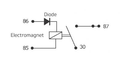
Make continuity checks across the electromagnet first, usually from pin 86 (positive) to pin 85 (negative). If a diode appears in the circuit use the diode check on the multimeter (Volts scale) in the direction of current flow. If there is no diode, use the resistance check facility. An open circuit or unusually high resistance value indicates a faulty relay.
To check the switch side, apply a 12 Volt supply between pins 86 and 85. With the supply connected, the relay should be heard to click and there should be continuity between pins 30 and 87. An open circuit indicates a faulty relay.