Removal
| PART NUMBER | TOOL NAME | |
| HD-45968 | FAT JACK | |
1. Position motorcycle on a suitable lift.
2. Remove the exhaust system. See 4.13 EXHAUST SYSTEM: XL MODELS or 4.14 EXHAUST SYSTEM: XR 1200X.
3. XR 1200X: Remove the air box assembly. See 4.3 AIR CLEANER ASSEMBLY, XR 1200X.
4. Loose the rear axle and drive belt. See 5.6 DRIVE BELT.
5. XL Models with Forward Mount Controls: Remove both forward control assemblies. See 2.41 RIDER FOOT CONTROLS: XL FORWARD CONTROLS.
6. Support front of engine with FAT JACK (Part No. HD-45968) and suitable blocks.
7. See Figure 2-167. Remove screw (4) securing upper front stabilizer link (2) to stabilizer link bracket (3).
8. See Figure 2-168. Remove screw (3) securing lower front stabilizer link (1) to stabilizer link bracket (2).
9. See Figure 2-169. Remove screw (4) from left end of rear stabilizer link (1) and ground strap (2). Remove spacer (5).
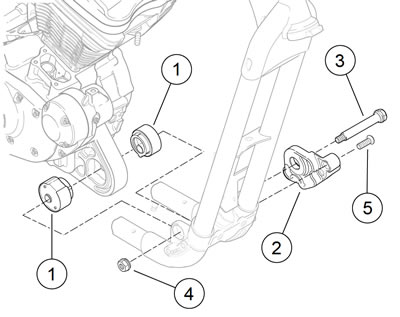
Note. See Figure 2-170. Jack the engine up or down to remove bolt (3).

Figure 2-170. Front engine mount/isolator: 1. Isolator; 2. Front isolator mount; 3. Bolt; 4. Nut; 5. Screw (2)
10. Remove nut (4) and bolt (3) from front engine mount/isol-ator assembly.
11. Remove screws (5) from front isolator mount (2) on left side of motorcycle. Remove isolator mount and left front isolator (1).
12. Without damaging the wire harness caddy, raise the front of the engine.
13. Without damaging the frame downtube, carefully pry front end of engine to the left approximately 1.0 in (25.4 mm).
14. Remove the right front isolator (1) from the crankcase.
Installation
| PART NUMBER | TOOL NAME | |
| HD-45968 | FAT JACK | |
| FASTENER | TORQUE VALUE | |
| Isolator, front, mounting bracket screw | 25-35 ft·lbs | 33.9-47.5 Nm |
| Engine mount, front, bolt | 95-105 ft·lbs | 129-142 Nm |
| Stabilizer link screw | 25-35 ft·lbs | 33.9-47.5 Nm |
| Stabilizer link, upper front, frame bracket mounting screw | 25-35 ft·lbs | 33.9-47.5 Nm |
| Stabilizer link screw | 25-35 ft·lbs | 33.9-47.5 Nm |
1. See Figure 2-170. Install both front isolators (1) in engine mounting boss on front of crankcase. Note that each isolator has a half-moon tab and fits into engine mounting boss in only one way. Push engine to the right until right isolator contacts frame boss.
2. Install front isolator mount (2) over left front isolator.
3. Install screws (5) through front isolator mount and thread into frame. Tighten to 25-35 ft·lbs (33.9-47.5 Nm).
4. Insert bolt (3) through front isolator/engine mount assembly from left side. Thread nut (4) onto bolt. Tighten to 95-105 ft·lbs (129-142 Nm).
5. See Figure 2-168. Attach lower front stabilizer link (1) to bracket (2) with screw (3). Tighten to 25-35 ft·lbs (33.947.5 Nm).
6. See Figure 2-167. Attach upper front stabilizer link (2) to bracket (3) with screw (4). Tighten to 25-35 ft·lbs (33.947.5 Nm).
7. See Figure 2-169. Install screw (4) through free end of ground strap (2), rear stabilizer link (1), spacer (5), and into engine crankcase. Tighten to 25-35 ft·lbs (33.9-47.5 Nm).
8. Remove FAT JACK (Part No. HD-45968) and blocks from under engine.
9. Forward Mount Controls: Install both forward control assemblies. See 2.41 RIDER FOOT CONTROLS: XL FORWARD CONTROLS.
10. Install the exhaust system. See 4.13 EXHAUST SYSTEM: XL MODELS or 4.14 EXHAUST SYSTEM: XR 1200X.
11. XR 1200X: Install the air box assembly. See 4.3 AIR CLEANER ASSEMBLY, XR 1200X.
12. Adjust the drive belt and tighten the rear axle. See 5.6 DRIVE BELT.
