
Removal and disassembly
Clutch cable: lower
Warning! To prevent accidental vehicle start-up, which could cause death or serious injury, remove main fuse before proceeding.
1. Remove main fuse.
2. Mid-mount Controls: Remove left side rider footrest and mounting bracket assembly. See 2.40 RIDER FOOT CONTROLS: XL MID-MOUNT CONTROLS or2.42 RIDER FOOT CONTROLS: XR 1200X.
3. See Figure 2-179. Slide rubber boot (1) on clutch cable adjuster (2) upward to expose adjuster mechanism. Loosen jamnut (3) from adjuster. Turn adjuster to shorten cable housing until there is a large amount of free play at clutch hand lever. See 1.11 CLUTCH.
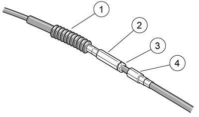
Figure 2-179. Clutch cable adjuster mechanism: 1. Rubber boot; 2. Cable adjuster; 3. Jamnut; 4. Cable end
4. See Figure 2-180. Remove six screws (1) and clutch inspection cover (2). Exercise caution to avoid damaging or dislodging quad ring (7) from groove in primary cover (9).
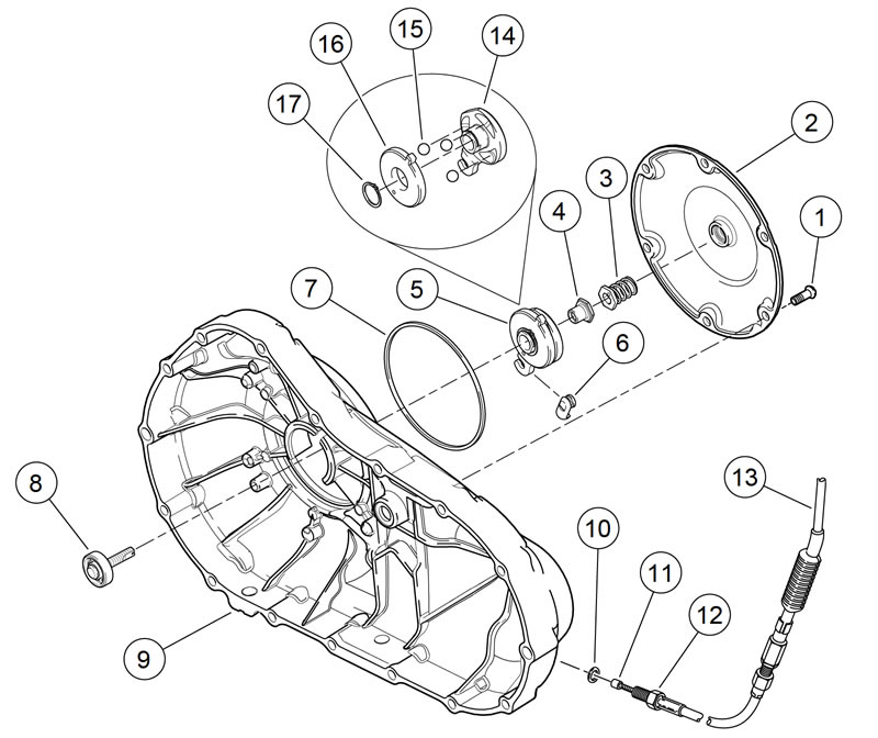
Figure 2-180. Clutch release mechanism: 1. Screw (6); 2. Clutch inspection cover; 3. Hex lockplate and spring; 4. Nut; 5. Ramp assembly (see items 14-17); 6. Coupling; 7. Quad ring; 8. Clutch adjusting screw assembly; 9. Primary cover; 10. O-ring; 11. Clutch cable end; 12. Cable end fitting; 13. Clutch cable; 14. Outer ramp; 15. Ball (3); 16. Inner ramp; 17. Retaining ring
5. Slide hex lockplate with attached spring (3) from flats of adjusting screw assembly (8).
6. Turn adjusting screw assembly clockwise to release ramp assembly (5) and coupling (6). As the adjusting screw is turned, ramp assembly moves forward. Remove nut (4) from end of adjusting screw.
7. Remove hook of ramp from cable coupling. Remove clutch cable end (11) from slot in coupling. Remove coupling and ramp assembly.
8. Remove cable end fitting (12) and clutch cable (13) lower section from primary cover. Remove O-ring (10) from cable end fitting. Discard O-ring.
9. Clean all metal parts in a non-volatile cleaning solution or solvent.
Clutch lever and cable: upper
1. See Figure 2-181. Remove retaining ring (8) and pivot pin (7). Discard retaining ring.
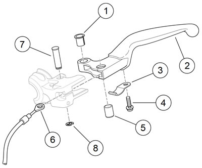
Figure 2-181. Clutch lever and cable: 1. Bushing; 2. Lever; 3. Anti-rattle spring; 4. Screw; 5. Clutch cable pin; 6. Clutch cable; 7. Pivot pin; 8. Retaining ring
2. Remove clutch lever (2) from clutch lever bracket.
3. Remove clutch cable pin (5). Disconnect clutch cable (6) upper section from lever.
Note. Remove the bushing from the top of the lever.
4. Remove bushing (1) from clutch lever.
5. Remove screw (4) and anti-rattle spring (3).
Clutch hand control
Note. XL 1200X: Leave the turn signals and brackets installed.
1. All Models except XL 1200X: Loosen the set screw. Remove the turn signal assembly from the clutch lever bracket. See 6.18 FRONT TURN SIGNALS, All Except XL 1200X.
2. See Figure 2-182. Loosen and remove the locknut (1), lockwasher (2) and mirror (3).

Figure 2-182. Clutch hand control clamp and bracket (typical): 1. Locknut; 2. Washer; 3. Mirror; 4. Fastener; 5. Washer; 6. Nylon retainer; 7. Clamp; 8. Bracket
Note. Loosen the two screws of the left handlebar switch housing to remove clutch control clamp and clutch lever bracket.
3. See Figure 2-182. Loosen the two screws (4) and washers (5) with nylon retainers (6) to remove the clutch control clamp (7).
4. Remove the clutch lever bracket (8).
Assembly and installation
| FASTENER | TORQUE VALUE | |
| Handlebar control lever clamp screw | 108-132 in·lbs | 12.2-14.9 Nm |
| Mirror stem locknut | 96-144 in·lbs | 10.9-16.3 Nm |
| Turn signal clamp, front, screw | 96-120 in·lbs | 10.9-13.6 Nm |
| Switch housing screw | 35-45 in·lbs | 4.0-5.1 Nm |
| Clutch lever anti-rattle spring screw | 8-13 in·lbs | 0.9-1.5 Nm |
| Clutch cable fitting | 36-108 in·lbs | 4.1-12.2 Nm |
| Clutch inspection cover screws | 90-120 in·lbs | 10.2-13.6 Nm |
| Footrest mount fastener | 45-50 ft·lbs | 61-68 Nm |
Clutch hand control
1. Position clutch control clamp and clutch lever bracket onto left handlebar. Hold clamp and bracket assembly firmly against left handlebar switch housing.
2. Secure components to left handlebar using two screws and washers and retainers. Tighten to 108-132 in·lbs (12.2-14.9 Nm).
Notes:
- Adjust the mirrors for rider vision.
- Adjust the mirrors to not strike the fuel tank on lock to lock handlebar turns.
XL 1200X: see figure 2-183.
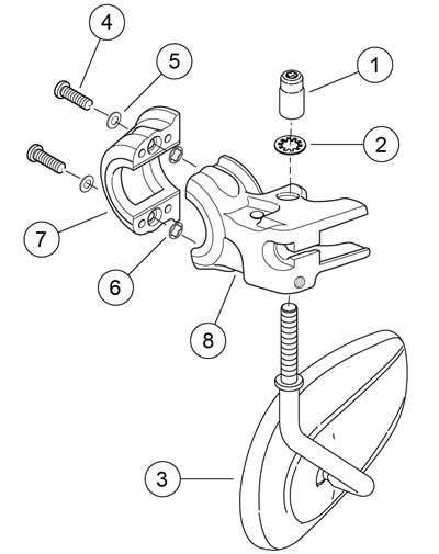
Figure 2-183. Clutch hand control bracket: XL 1200X: 1. Locknut; 2. Lockwasher; 3. Mirror; 4. Fastener; 5. Washer; 6. Nylon retainer; 7. Clamp; 8. Bracket
3. Install mirror with locknut and lockwasher. Tighten locknut to 96-144 in·lbs (10.9-16.3 Nm).
4. All Models except XL 1200X: Install turn signal and secure with set screw. See 6.18 FRONT TURN SIGNALS, All Except XL 1200X.
5. Position so turn signal lens faces directly forward. Verify turn signal does not strike fuel tank when the handlebar is turned full left. Tighten set screw to 96-120 in·lbs (10.913.6 Nm).
Note. If two screws of left handlebar switch housing were loosened during clutch hand control removal, tighten to 35-45 in·lbs (4.0-5.1 Nm).
Clutch lever and clutch cable: upper
1. Install anti-rattle spring and screw onto clutch lever. Tighten screw to 8-13 in·lbs (0.9-1.5 Nm).
2. Install bushing in clutch lever. Bushing has a collar on one end and must be installed from top of lever.
3. Connect end of clutch cable upper section to clutch lever using clutch cable pin.
4. Position lever within clutch lever bracket, install pivot pin and secure with new retaining ring.
Clutch cable: lower
1. XL Models: See Figure 2-184. Route the clutch cable (3):
- a. Forward from clutch lever (1).
- b. Downward to left front fork slider tube. Refer to Table 2-26.
- c. Through two clips (6) on left front frame downtube.
- d. Rearward to the primary cover (4).
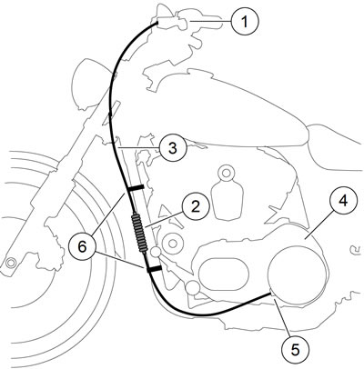
Figure 2-184. Clutch cable routing: XL models: 1. Clutch lever; 2. Cable adjuster boot; 3. Clutch cable; 4. Primary cover; 5. Cable end fitting; 6. Clip (2)
2. XR 1200X: See Figure 2-185. Route the clutch cable:
- a. Down between the fork tubes and clamps.
- b. Downward to inboard side of the left front fork slider tube.
- c. Through the two clips in the oil cooler mounting bracket.
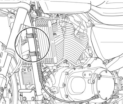
Figure 2-185. Clutch cable clips: XR 1200X
Note. Check that cable is not pinched between the lower steering head bracket and frame and the left and right fork stops.
Table 2-26. Clutch cable lower routing around left fork slider
| MODEL | ROUTE | NOTES |
| XL 883L | Outboard | - |
| XL 883N | Outboard | - |
| XL 883R | Outboard | - |
| XL 1200C/C ANV XL 1200CP/CA/CB | Inboard | Through the clutch cable guide |
| XL 1200X | Inboard | - |
| XL 1200V | Inboard | - |
3. See Figure 2-180. Install new O-ring (10) over cable end fitting (12) of clutch cable (13) lower section. Screw fitting into primary cover (9). Tighten to 36-108 in·lbs (4.1-12.2 Nm).
4. Install coupling (6) over cable end (11) with the rounded side inboard and the ramp connector button outboard. With retaining ring side of ramp assembly (5) facing inward, place hook of ramp around coupling button. Rotate assembly counterclockwise until tang on inner ramp (16) fits in slot of primary cover.
5. Thread nut (4) on adjusting screw assembly (8) until slot of screw is accessible with a screwdriver. Fit nut hex into recess of outer ramp (14). Turn adjusting screw counterclockwise until resistance is felt. Then back off adjusting screw 1/4 turn.
6. Install hex lockplate with spring (3) onto flats of adjusting screw assembly (8). If necessary, turn adjusting screw clockwise slightly so that lockplate slides onto flats while also fitting within recess of outer ramp.
7. Verify that quad ring (7) is fully seated in groove of primary cover (9). Install clutch inspection cover (2) and secure with six screws (1). Tighten screws in a cross pattern to 90-120 in·lbs (10.2-13.6 Nm).
8. Models with Mid-mount Controls: Install left side rider footrest and mounting bracket assembly. Tighten footrest bracket mounting screws to 45-50 ft·lbs (61-68 Nm). See 2.40 RIDER FOOT CONTROLS: XL MID-MOUNT CONTROLS or 2.42 RIDER FOOT CONTROLS: XR 1200X.
9. Install main fuse.