XL models except XL 1200V
| FASTENER | TORQUE VALUE | |
| Air cleaner breather screw | 84-120 in·lbs | 9.5-13.6 Nm |
| Air filter screw | 40-60 in·lbs | 4.5-6.8 Nm |
| Air cleaner cover screw | 36-60 in·lbs | 4.1-6.8 Nm |
Removal
1. See Figure 4-1. Remove two screws (1) and trim insert (2) from air cleaner cover (3).

Figure 4-1. Air cleaner assembly: All XL except XL 1200V: 1. Screw (2); 2. Trim insert; 3. Cover; 4. Seal; 5. Screw (3); 6. Filter element (includes item 7); 7. Filter element gasket; 8. O-ring (2); 9. Breather screw (2); 10. Backplate; 11. Gasket
2. Remove air cleaner cover from air cleaner backplate (10).
3. Remove air cleaner seal (4) from air cleaner cover.
4. Remove three screws (5). Remove air filter element (6) and gasket (7). Discard gasket.
5. Remove O-rings from the breather screws (9). Discard the O-rings.
Notice: Install air filter before running engine. Failure to do so can draw debris into the engine and could result in engine damage.
6. Remove two breather screws (9) from air cleaner backplate.
7. Remove air cleaner backplate and gasket (11).
Installation
1. See Figure 4-1. Position new gasket (11) and air cleaner backplate (10) at induction module air inlet.
2. Apply LOCTITE 243 MEDIUM STRENGTH THREADLOCKER AND SEALANT (blue) to existing screws or use new breather screws (9). Install air cleaner backplate to engine heads. Tighten to 84-120 in·lbs (9.5-13.6 Nm).
3. To prevent damage, apply a thin coat of engine oil to Orings (8). Install O-rings to breather tubes.
4. Position new gasket (7) on air cleaner backplate. Line up gasket holes with backplate holes.
5. Install air filter element (6) onto backplate. Secure with three new screws (5) or apply LOCTITE 243 MEDIUM STRENGTH THREADLOCKER AND SEALANT (blue) to existing screws. Tighten to 40-60 in·lbs (4.5-6.8 Nm).
6. Install air cleaner seal (4) on air cleaner cover (3). Fit the air cleaner seal around the entire edge of cover.
7. Install air cleaner cover onto backplate. Do not pinch or distort seal.
8. Install trim insert (2) and air cleaner cover with two screws (1). Tighten to 36-60 in·lbs (4.1-6.8 Nm).
XL 1200V
| FASTENER | TORQUE VALUE | |
| Air cleaner breather screw | 84-120 in·lbs | 9.5-13.6 Nm |
| Air filter screw | 40-60 in·lbs | 4.5-6.8 Nm |
| Air cleaner cover screw | 36-60 in·lbs | 4.1-6.8 Nm |
Removal
1. See Figure 4-2. Remove the cover screw (1).

Figure 4-2. Air cleaner assembly: XL 1200V: 1. Screw; 2. Cover; 3. Seal; 4. Screw (3); 5. Filter element; 6. Breather screw; 7. Backplate; 8. Backplate gasket; 9. Filter gasket; 10. O-ring
2. Remove the cover (2) and the seal (3).
3. Remove the three screws (4), the air filter element (5) and gasket (9).
4. Remove the O-rings (10). Discard the O-rings.
5. Remove the two breather screws (6).
6. Remove the backplate (7) and gasket (8).
7. Inspect and replace parts as necessary.
8. Clean or replace the air filter element as necessary. See 1.7 AIR FILTER, Cleaning Filter Element.
Installation
1. See Figure 4-2. Install the gasket (8) and backplate (7).

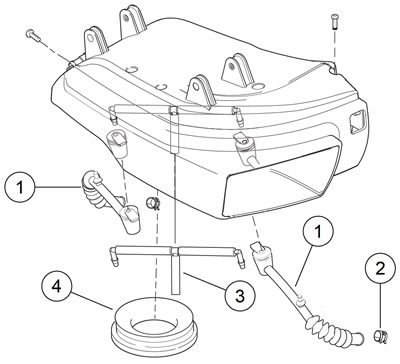
Figure 4-3. Air box: XR 1200X: 1. Breather hose; 2. Clamp; 3. Breather hose assembly; 4. Coupling
2. Apply LOCTITE 243 MEDIUM STRENGTH THREADLOCKER AND SEALANT (blue) to existing screws or use new breather screws (6). Install the breather screws. Tighten to 84-120 in·lbs (9.5-13.6 Nm).
3. Apply engine oil to new O-rings (10). Install the O-rings on the breather tubes.
4. Install the filter gasket (9).
5. Install the air filter element (5) and screws (4). Tighten to 40-60 in·lbs (4.5-6.8 Nm).
6. Fit the cover (2) to the seal (3).
7. Install the cover and screw (1). Tighten to 36-60 in·lbs (4.1-6.8 Nm).
XR1200X
Removal
1. Remove the fuel tank. See 4.5 FUEL TANK: XR 1200X.
2. HDI Models: Disconnect active intake solenoid connector [178].
Note. Leave the rubber coupling attached to the induction module.
3. Lift the air box off induction module.
4. See Figure 4-3. Disconnect the crankcase breather hoses from the front and rear rocker cover fittings.
5. Remove the air box assembly.
6. Remove the cover and air filter element as necessary. See 1.7 AIR FILTER, XR 1200X.
7. Replace damaged parts as necessary.
Installation
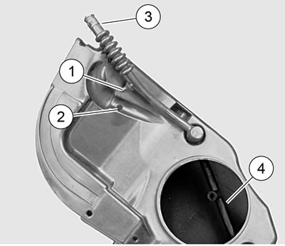
Note. See Figure 4-4. Check that the breather hose assembly (4) inside the air box does not interfere with the active air solenoid flapper.

Figure 4-4. Front crankcase vent hose: 1. Anchor barb; 2. Anchor hole in air box; 3. Vent hose clamp; 4. Breather hose assembly
1. Install all hoses.
2. Snap the anchor barb (1) of the front crankcase vent hose in the hole (2) in the air box bottom.
3. If removed, install the air filter element and cover. See 1.7 AIR FILTER, XR 1200X.
4. Seat the rubber coupling on the induction module.
5. Verify that the clamps are in place.
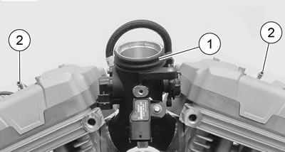
6. See Figure 4-5. Hold the air box close. Connect crankcase vent hoses to the fittings (2) on the front and rear rocker covers.

Figure 4-5. Air box connections: 1. Induction module throat; 2. Fittings on rocker covers
Note. The edge of hole in air box must encircle the groove in the coupling.
7. Seat the coupling into the air box opening.
8. HDI Models: Connect the active intake solenoid connector [178].
9. Install the fuel tank. See 4.5 FUEL TANK: XR 1200X.
