Removal
| PART NUMBER | TOOL NAME | |
| HD-45967 | SHOP DOLLY | |
| HD-45968 | FAT JACK | |
1. XR 1200X: Remove the air box assembly. See 4.3 AIR CLEANER ASSEMBLY, XR 1200X.
2. Remove exhaust system. See 4.13 EXHAUST SYSTEM: XL MODELS or 4.14 EXHAUST SYSTEM: XR 1200X.
3. With the aid of a FAT JACK (Part No. HD-45968), support motorcycle on SHOP DOLLY (Part No. HD-45967).
Note. Position vehicle on SHOP DOLLY so that FAT JACK may be used (with the aid of suitable blocks) to support engine when rear engine mount is removed.
4. Remove sprocket cover.
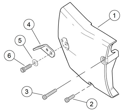
- a. XL Models: See Figure 2-171. Remove screw (6), washer (5) and exhaust pipe clamp bracket (4). Remove two screws (2, 3). Remove sprocket cover (1).
- b. XR 1200X: See Figure 2-172. Remove screw and washer (2) and screws (3, 4). Remove sprocket cover (1).

Figure 2-171. Sprocket cover: XL models: 1. Sprocket cover; 2. Screw; 3. Screw; 4. Exhaust pipe clamp bracket; 5. Washer; 6. Screw

Figure 2-172. Sprocket cover: XR 1200X: 1. Sprocket cover; 2. Rear screw and washer; 3. Front screw; 4. Lower screw
5. Loosen rear axle and remove rear drive belt. See 5.6 DRIVE BELT.
6. XL Models with Passenger Footrests: Remove left passenger footrest assembly. See 2.43 PASSENGER FOOTRESTS.
7. XR 1200X: Remove left and right rider controls and brackets. See 2.42 RIDER FOOT CONTROLS: XR 1200X.
8. Unbolt rear brake master cylinder remote reservoir. Do not disconnect hose from reservoir. Secure reservoir to vehicle in an upright position, out of the way. See 2.13 REAR BRAKE MASTER CYLINDER RESERVOIR.
9. Support rear fork assembly using vehicle tiedown straps.
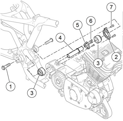
10. See Figure 2-173. Remove rear fork pivot bolts (1).

Figure 2-173. Rear engine mount/isolator: typical (XL models): 1. Bolt (2); 2. Rear isolator mount; 3. Isolator (2); 4. Rear fork pivot shaft; 5. Rear pivot lockplate; 6. Screw (3); 7. Screw (2)
11. Pull rear fork back far enough to clear rear engine mounts and isolators.
12. Motorcycles Equipped with EVAP: Remove EVAP canister and mounting bracket. See 4.20 EVAPORATIVE EMISSIONS CONTROL, Charcoal Canister.
13. See Figure 2-169. Remove screws (3, 4) securing rear stabilizer link (1). Remove stabilizer link, ground strap (2), and spacer (5).
14. See Figure 2-167. Remove screw (4) securing upper front stabilizer link (2) to stabilizer link bracket (3).
15. See Figure 2-168. Remove screw (3) securing lower front stabilizer link (1) to stabilizer link bracket (2).
16. Support rear of engine with lifting device and suitable blocks.
17. See Figure 2-173. Remove two screws (7) securing rear isolator mount (2) to left side of frame. Remove isolator mount and left isolator (3).
18. Remove three screws (6) securing rear pivot lockplate (5) to rear of engine case. Remove lockplate and rear fork pivot shaft (4).
Note. Engine may need to be jacked up or down slightly to aid in removing pivot shaft.
19. Carefully pry rear end of engine to the left approximately 1.0 in (25.4 mm). Remove right rear isolator (3) from frame.
Installation
| PART NUMBER | TOOL NAME |
| HD-45968 | FAT JACK |
| FASTENER | TORQUE VALUE | |
| Sprocket cover, forward and lower screw | 80-120 in·lbs | 9.0-13.6 Nm |
| Isolator, front, mounting bracket screw | 25-35 ft·lbs | 33.9-47.5 Nm |
| Stabilizer link, upper front, frame bracket mounting screw | 25-35 ft·lbs | 33.9-47.5 Nm |
| Stabilizer link, lower front, frame bracket mounting screw | 25-35 ft·lbs | 33.9-47.5 Nm |
| Stabilizer link screw | 25-35 ft·lbs | 33.9-47.5 Nm |
| Fork, lower front, pivot/engine mount bolt | 60-70 ft·lbs | 81.4-95.0 Nm |
| Exhaust pipe clamp bracket screw | 30-33 ft·lbs | 40.7-44.7 Nm |
| Sprocket cover, forward and lower screws | 80-120 in·lbs | 9.0-13.6 Nm |
| Sprocket cover, rear screw | 30-33 ft·lbs | 40.7-44.7 Nm |
| Sprocket cover, forward and lower screws | 80-120 in·lbs | 9.0-13.6 Nm |
1. See Figure 2-173. Install new right rear isolator (3) into frame, lining up tabs on isolator with slots in frame. Slide rear end of engine to the right until engine mounting boss on rear of crankcase contacts right isolator.
2. Slide rear fork pivot shaft (4) through engine mounting boss.
Note. Engine may need to be moved slightly in one direction or another to align pivot shaft with isolator.
3. Install rear pivot lockplate (5) over pivot shaft with ridges on lockplate engaging flats on pivot shaft flange. Secure to crankcase with three screws (6). Tighten to 80-120 in·lbs (9.0-13.6 Nm).
4. Install new left rear isolator (3) on rear fork pivot shaft.
5. Place rear isolator mount (2) over left rear isolator, lining up tabs on isolator with slots in isolator mount. Install screws (7). Tighten to 25-35 ft·lbs (33.9-47.5 Nm).
6. Remove FAT JACK (Part No. HD-45968) and blocks.
7. See Figure 2-167. Attach upper front stabilizer link (2) to bracket (3) with screw (4). Tighten to 25-35 ft·lbs (33.947.5 Nm).
8. See Figure 2-168. Attach lower front stabilizer link (1) to bracket (2) with screw (3). Tighten to 25-35 ft·lbs (33.947.5 Nm).
9. See Figure 2-169. Install ground strap (2) and rear stabilizer link (1) to right side frame using short screw (3). Install free end of ground strap, stabilizer link and spacer (5) into engine case using long screw (4). Tighten screws to 2535 ft·lbs (33.9-47.5 Nm).
Note. XR 1200X: Check that the ground strap does not contact the rear stop switch harness before tightening stabilizer link screws.
10. Motorcycles Equipped with EVAP: Install EVAP canister and mounting bracket. See 4.20 EVAPORATIVE EMISSIONS CONTROL, Charcoal Canister.
11. See Figure 2-173. Slide rear fork forward into position. Install rear fork pivot/engine mount bolts (1). Tighten to 60-70 ft·lbs (81.4-95.0 Nm). Remove vehicle tiedown straps supporting rear fork.
12. Install rear brake master cylinder remote reservoir. See 2.13 REAR BRAKE MASTER CYLINDER RESERVOIR.
13. XL Models equipped with Passenger Footrests: Install left passenger footrest assembly. See 2.43 PASSENGER FOOTRESTS.
14. XR 1200X: Install left and right rider foot controls and brackets. See 2.42 RIDER FOOT CONTROLS: XR 1200X.
15. Install and adjust rear drive belt and tighten rear axle. See 5.6 DRIVE BELT.
16. XL Models: Install sprocket cover.
- a. See Figure 2-171. Install sprocket cover (1). Secure with two screws (2, 3). Note that long screw goes in top hole, short screw in bottom hole. Do not tighten screws at this time.
- b. Install exhaust pipe clamp bracket (4), washer (5) and screw (6). Tighten to 30-33 ft·lbs (40.7-44.7 Nm). Now tighten screws (2, 3) to 80-120 in·lbs (9.0-13.6 Nm).
17. XR 1200X: Install sprocket cover.
- a. See Figure 2-172. Tighten screw (2) to 30-33 ft·lbs (40.7-44.7 Nm).
- b. Tighten screws (3, 4) to 80-120 in·lbs (9.0-13.6 Nm).
18. Install exhaust system. See 4.13 EXHAUST SYSTEM: XL MODELS or 4.14 EXHAUST SYSTEM: XR 1200X.
19. XR 1200X: Install the air box assembly. See 4.3 AIR CLEANER ASSEMBLY, XR 1200X.
