Note. When engine is removed from chassis, do not lay engine on primary side. Laying engine on primary side will damage the clutch cable end fitting. If fitting is damaged, clutch cable must be replaced.
Disassembly
| PART NUMBER | TOOL NAME |
| B-45655, HD-42720- 2, HD-46663 | CRANKCASE BEARING REMOVER/INSTALLER WITH ADAPTER |
| CJ 114 | SNAP-ON BODY DENT PULLER |
| J-5586-A | TRANSMISSION SHAFT RETAINING RING PLIERS |
1. Disassemble crankcase, see 3.17 BOTTOM END OVERHAUL: DISASSEMBLY, Crankcase.
Note. Remove either the pinion shaft bearing or the left main bearing with this procedure.
2. See Figure 3-121. Pinion shaft bearing assembly (3) will remain on pinion shaft (2) when flywheel assembly (1) is removed from right crankcase. Using TRANSMISSION SHAFT RETAINING RING PLIERS (Part No. J-5586-A), remove retaining ring (4) and slip bearing off pinion shaft.

Figure 3-121. Removing pinion shaft bearing retaining ring: 1. Flywheel assembly; 2. Pinion shaft; 3. Pinion shaft bearing assembly; 4. Retaining ring
Note. The sprocket shaft inner race is not replaceable. Replace crankshaft if race is worn or damaged.
3. See Figure 3-122. Remove outer left main bearing retaining ring.
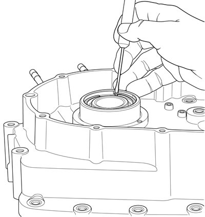
Figure 3-122. Removing left main oil seal retaining ring
4. Remove left main oil seal from left crankcase using SNAP-ON BODY DENT PULLER (Part No. CJ 114).
5. Remove thrust washer next to left main bearing.
6. See Figure 3-123. Remove left main bearing retaining ring from the inside of the left crankcase.
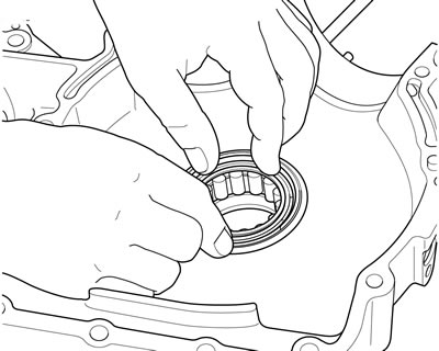
Figure 3-123. Removing left main bearing retaining ring
Note. Press the left main bearing from the outside of the left crankcase toward the inside. A shoulder in the left crankcase prevents the bearing from being pressed towards the outside.
7. See Figure 3-124. Using CRANKCASE BEARING REMOVER/INSTALLER WITH ADAPTER (Part No. B-45655, HD-42720-2, HD-46663), press left main bearing out of the left crankcase.
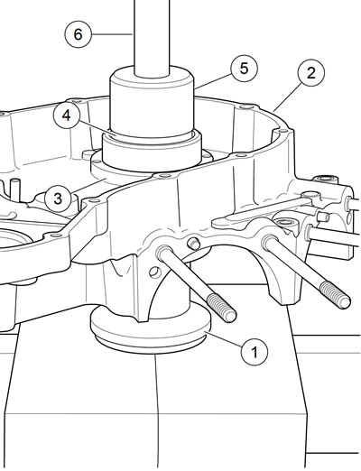
Figure 3-124. Removing left main bearing from crankcase: 1. Support tube; 2. Left crankcase; 3. Crankshaft bearing bore; 4. Adapter; 5. Pilot/driver; 6. Press ram
- a. Place support tube (1) on press bed with recessed cup end facing up.
- b. With the outboard side of the left crankcase (2) facing upward, position crankshaft bearing bore (3) over support tube.
- c. Place adapter (4) over left main bearing. Insert pilot/driver (5) through adapter, through left main bearing and into support tube.
- d. Carefully apply pressure with press ram (6) until left main bearing drops free.
Fitting pinion bearings
| PART NUMBER | TOOL NAME |
| HD-34902-7 | END CAP |
| J-21686-12 | FORCING SCREW |
| J-7830-5 | BRIDGE |
| SNAP-ON TOOLS STOCK NO. CJ950 | BEARING SEPARATOR |
Outer and inner races
The outer race is a pressed-in bushing in the right crankcase. The inner race is pressed on the pinion shaft.
See Figure 3-125. To remove pinion shaft inner race, use BEARING SEPARATOR (Part No. Snap-on Tools Stock No. CJ950), three items from END CAP (Part No. HD-34902-7), BRIDGE (Part No. J-7830-5) and FORCING SCREW (Part No. J-21686-12), and two bolts. Apply heat to race to aid removal.

Figure 3-125. Pulling pinion shaft inner bearing: 1. Forcing screw; 2. Bridge; 3. End cap; 4. Bolts (2); 5. Bearing separator; 6. Flywheel support fixture
Pinion bearing selection is based on the largest measured outside diameter (OD) of the inner race and the smallest measured inside diameter (ID) of the outer race (crankcase bushing).
A running clearance of 0.0002-0.0008 in (0.005-0.020 mm) is established during crankcase set or flywheel assembly replacement and engine rebuild.
See Figure 3-126. Installed inner races are identified at the factory as shown.
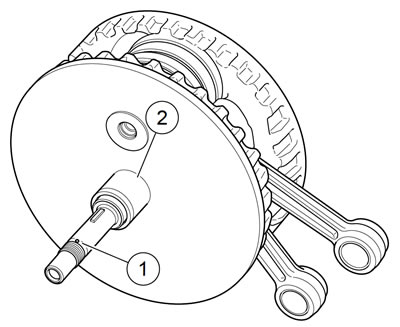
Figure 3-126. Factory inner race sizes
See Figure 3-128. Outer races are identified at the factory as shown.
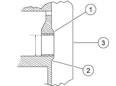
Figure 3-128. Factory outer race sizes: 1. Outer race; 2. Stamped class no; 3. Right crankcase
Note. The different sizes of crankcase sets and flywheel assemblies do not have separate part numbers. Replacement crankcase sets can have a class 1, 2 or 3 pinion outer race. Replacement flywheel assemblies can have either a class A or B inner race.
Table 3-35. Inner race specifications
| RACE OD | CLASS | IDENTIFICATION* | |
| in | mm | ||
| 1.2498-1.2500 | 31.745-31.750 | A | White |
| 1.2496-1.2498 | 31.740-31.745 | B | Green |
* Paint dot on end of spline.
Bearing selection
See Figure 3-127. Pinion bearing roller OD cannot be measured to required accuracy with a micrometer. Select bearings using the identification information given for inner and outer races and bearings. Refer to Table 3-38.

Figure 3-127. Bearing roller OD (A)
Note. If either inner or outer race show wear, measure both races to confirm correct bearing fit of 0.0002-0.0008 in (0.005-0.020 mm). The service wear limit of the outer race ID is 1.5656 in (39.776 mm).
Table 3-36. Roller specifications
| ROLLER OD (A) | IDENTIFICATION (PACKAGE COLOR) |
| Largest | Red |
| Blue | |
| White (gray) | |
| Smallest | Green |
Table 3-37. Outer race specifications
| RACE ID | CLASS NO. | STAMPED IDENTIFICATION* | |
| in | mm | ||
| 1.5646-1.5648 | 39.741-39-746 | 1 | 1 |
| 1.5648-1.5650 | 39.746-39.751 | 2 | 2 |
| 1.5650-1.5652 | 39.751-39.756 | 3 | 3 |
* Stamped number inside crankcase near race.
Table 3-38. Pinion shaft bearing selection
| FACTORY STAMPED NUMBER | OUTER RACE ID | BEARING SIZE AS IDENTIFIED BY COLOR CODING | |||
| in | mm | ||||
| 1.5654-1.5656 | 39.761-39.766 | Red | |||
| 1.5652-1.5654 | 39.756-39.761 | Red | Blue | ||
| 3 | 1.5650-1.5652 | 39.751-39.756 | Red | Blue | White-gray |
| 2 | 1.5648-1.5650 | 39.746-39.751 | Blue | White-gray | Green |
| 1 | 1.5646-1.5648 | 39.741-39.746 | White-gray | Green | |
| Inner Race OD (in) | 1.2496-1.2498 | 1.2498-1.2500 | 1.2500-1.2502 | ||
| Inner Race OD (mm) | 31.740-31.745 | 31.745-31.750 | 31.750-31.755 | ||
| Factory Color Code | Green | White | |||
Note. Removal and installation of the inner and outer bearing races require the use of shop-made tools. See Figure 3-130, Figure 3-131, and Figure 3-132.

Figure 3-130. Pinion shaft outer race installation tool: 1. 2.00 in (50.8 mm); 2. 1.00 in (25.4 mm); 3. 1.560 in (39.62 mm); 4. 0.187 in (4.75 mm); 5. 5/16 drill
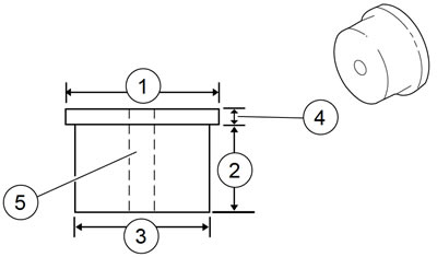
Figure 3-131. Pinion shaft outer race removal tool: 1. 1.70 in (43.2 mm); 2. 1.00 in (25.4 mm); 3. 1.560 in (39.62 mm); 4. 0.187 in (4.75 mm); 5. 5/16 drill
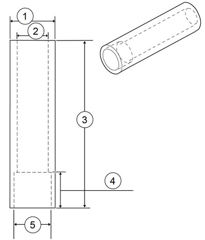
Figure 3-132. Pinion shaft inner race installation tool: 1. 1.50 in (38.1 mm); 2. 1.00 in (25.4 mm); 3. 5.50 in (139.7 mm); 4. 1.135-1.145 in (28.83-29.08 mm); 5. 1.262-1.272 in (32.05-32.31 mm)
1. Measure ID of outer race at four places with a dial bore gauge. Take measurement on ID where bearing rollers ride. Record the four measurements.
Table 3-39. Used pinion bearing outer race specifications
| ITEM | in | mm |
| Largest ID allowed | 1.5656 | 39.776 |
| Roundness of ID (within) | 0.0002 | 0.005 |
| Taper (within ) | 0.0002 | 0.005 |
2. If the largest measurement is largerthan 1.5656 in (39.776 mm) or the required lapping to remove wear marks would enlarge bore beyond 1.5656 in (39.776 mm), continue at Step 8. Refer to Table 3-39.
3. If the largest measurement is 1.5656 in (39.776 mm) or less, cover the cam bearings with masking tape to prevent debris from entering bearings. Assemble crankcase halves.
Note. The next step requires lapping the outer race. To keep sprocket shaft and pinion shaft bearings aligned, support the lap by an adaptor or pilot in the left crankcase.
4. Lap the outer race. The race must be lapped until all wear marks are removed. See 3.19 CRANKCASE, Lapping Engine Main Bearing Races.
5. After lapping race, again measure ID of race at four places and record the measurements.
6. Check measurements against the specifications listed in Table 3-39.
7. If lapping increased bore ID to larger than 1.5656 in (39.776 mm), goto next step. If roundness or taper do not meet specifications, continue lapping until specifications are met. If all specifications are met, continue at Step 10 to remove and size inner race.
Note. Always use the smallest outer race ID measurement and the largest OD inner race measurement when selecting bearings.
8. Press the outer race from the right crankcase. Press new outer race into crankcase flush with inside edge of cast-in insert.
9. The new outer race must be lapped slightly to true and align with left case bearing to specifications. Refer to Table 3-40. See 3.19 CRANKCASE, Lapping Engine Main Bearing Races.
Table 3-40. New pinion bearing outer race fit and finish
| ITEM | SPECIFICATION | |
| in | mm | |
| ID | 1.5646-1.5652 | 39.741-39.756 |
| Roundness within: | 0.0002 | 0.005 |
| Taper within: | 0.0002 | 0.005 |
| Surface finish | 16 RMS | |
10. See Figure 3-125. Pull inner race from pinion shaft using BEARING SEPARATOR (Part No. Snap-on Tools Stock No. CJ950), three items from END CAP (Part No. HD-34902-7), BRIDGE (Part No. J-7830-5) and FORCING SCREW (Part No. J-21686-12), and two bolts. Apply heat to race to aid removal.
11. See Figure 3-129. Press new inner race on pinion shaft using shop-made tool. When the tool bottoms against the flywheel, the correct inner race location is automatically established. The new inner race must be machined to dimension based on the finished lapped ID ofthe outer race. Refer to Table 3-38.
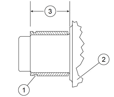
Figure 3-129. Inner race location: 1. Pinion shaft inner race; 2. Flywheel (gear side); 3. 1.135-1.145 in (28.83-29.08 mm)
Table 3-41. Inner race fit and finish
| ITEM | SPECIFICATION | |
| in | mm | |
| Roundness within: | 0.0002 | 0.005 |
| Taper within: | 0.0002 | 0.005 |
| Surface finish | 16 RMS | |
Inner bearing finish example
The following example illustrates how to determine the required inner race OD:
1. If smallest measured ID of outer race is 1.5651 in (39.754 mm), an inner race OD range of 1.2496-1.2504 in (31.74031.760 mm) is required. Refer to Table 3-38.
Note. Have machinist precision grind outer race to center or middle of required OD range. This will prevent grinding outer race undersize and gives a more easily achieved tolerance range.
2. Precision grind inner race OD to the middle ofthe desired range. Refer to Table 3-38.
3. Measure OD at four places. Verify that OD is to specification. Refer to Table 3-41.
4. For example purposes:
- a. The largest measured OD of inner race after grinding is 1.2499 in (31.747 mm) OD.
- b. With a 1.5651 in (39.754 mm) ID outer race and a 1.2499 in (31.747 mm) OD inner race, a blue bearing is required. Refer to Table 3-38.
Lapping engine main bearing races
| PART NUMBER | TOOL NAME |
| HD-46287 | LAPPING TOOL ADAPTER |
| HD-96710-40C | CRANKCASE MAIN BEARING LAPPING TOOL |
| HD-96718-87 | CRANKCASE MAIN BEARING LAP |
1. See Figure 3-133. Obtain CRANKCASE MAIN BEARING LAPPING TOOL (Part No. HD-96710-40C). Assemble CRANKCASE MAIN BEARING LAP (Part No. HD-9671887) to lapping handle.

Figure 3-133. Lapping pinion shaft main bearing
Note. Left main bearing must be installed in left crankcase to use LAPPING TOOL ADAPTER (Part No. HD-46287) in the next step. See 3.22 BOTTOM END OVERHAUL: ASSEMBLY Crankcase.
2. Assemble LAPPING TOOL ADAPTER (Part No. HD-46287) to left main bearing.
3. Secure right and left crankcase halves with three crankcase stud bolts (top center and bottom left and right).
4. Insert lap shaft with arbor assembled through pinion bearing bushing and into lapping tool adapter. Tighten arbor expansion collars using a length of 0.156 in (3.96 mm) rod as spanner until arbor begins to drag. Do not adjust arbor snug in bushing or bushing will bell. Belling is a condition where hole is larger at ends than it is in the center.
5. Withdraw arbor far enough to coat lightly with 220 grit lapping compound. Do not apply a heavy coat. Reposition lap in bushing and turn handle at moderate hand speed. Work lap back and forth in bushing, as it is revolved, to avoid grooving and tapering.
6. At frequent intervals, remove lap from crankcase, wash and inspect bushing. Lapping is completed when entire bushing surface has a dull, satin finish rather than a glossy, smooth appearance.
Warning! Compressed air can pierce the skin and flying debris from compressed air could cause serious eye injury. Wear safety glasses when working with compressed air. Never use your hand to check for air leaks or to determine air flow rates.
7. When finished, flush off lap tool using cleaning solvent and dry using compressed air. Apply fresh, light coat of fine lapping compound.
